
| Tweet |

Custom Search
|
|

|
||
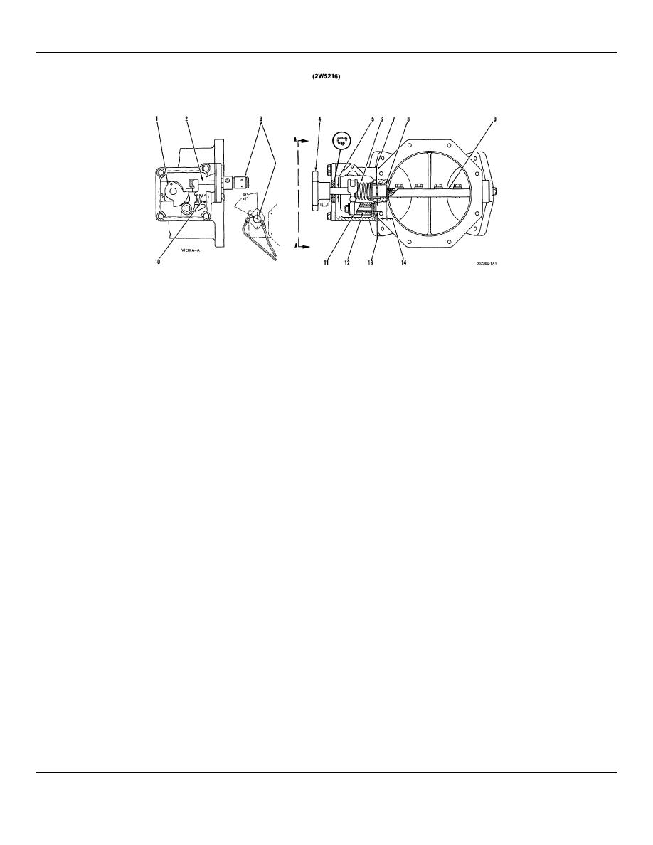 3500 ENGINE
SPECIFICATIONS
AIR INTAKE SHUTOFF
(1)
Latch.
(8)
Shaft assembly.
(9)
Plate assembly.
(2)
Shutoff cylinder rod.
(3)
Install shutoff cylinder as follows:
NOTE: With plate assembly (9) in closed (shutoff)
position, a 0.8 mm (.03 in.) feeler gauge must not pass
a.
Assemble shutoff cylinder on the flange at
between the plate assembly and the housing bore at any
the angle shown.
position.
b.
Tighten the nut that holds the shutoff
(10)
Lever return spring.
cylinder to the flange to a torque of .... 45
7 Nm (33 5 lb. ft.)
(11)
Lever.
(12)
Sleeve.
c.
Install the flange on the air shutoff housing.
Make sure cylinder rod (2) is engaged in the
(13)
Diameter of
notch of lever (11).
4.945 0.009 mm (.5995
sleeve..................
0004 in.)
NOTE: The cylinder vent hole, between the
ports, must be in the downward position.
Bore in bushing (after
assembly)........5.024 0.034 mm (.6026 .0014
(4)
Knob.
in.)
(5)
Diameter of shaft assembly
....... 15.88 0.05 mm (.625 .002 in.)
at seal
Bore in lever for
bushing.............7.009 0.009 mm (.6823 .0004
(6)
Air shutoff spring.
in.)
(7)
Diameter of shaft
assembly ....... 24.88 0.02 mm (.980 .001 in.)
NOTE : Install both bushings to a dimension of 0.8 0.3
mm (.03 .01 in.) below the surface of lever ends.
Bore in bushings for shaft assembly
25.017 0.040 mm
(after assembly)........
(14)
Dimension to install end of two bushings from
(1.0035 0016 in.)
machined
housing bore ...0.35 0.15 mm (.014 .006 in.)
Bores in housing for
bearings ....... 27.997 0.010 mm
(1.1230 .0004 in.)
NOTE: FOR TORQUE VALUES NOT GIVEN, SEE THE FIRST PAGE OF SPECIFICATIONS FOR
GENERAL TIGHTENING TORQUES
25
|
||
|
||


