
| Tweet |

Custom Search
|
|

|
||
 3500 ENGINE
SPECIFICATIONS
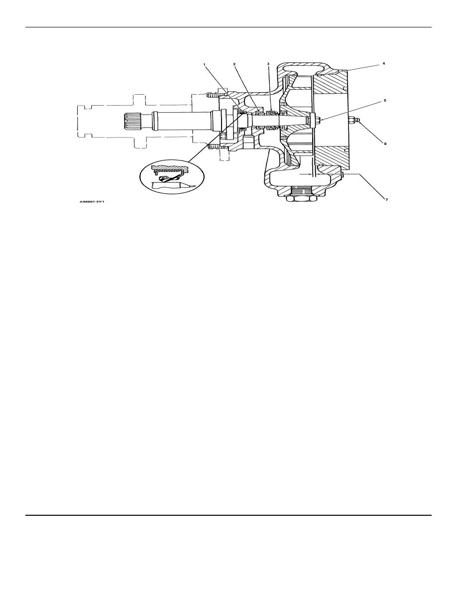
WATER PUMP
EARLIER WATER PUMP ILLUSTRATED
(1)
Oil seal. Put glycerin or clean engine oil on the
the bore for the seal.
lip of the seal. Assemble with the lip toward the
splined end of the pump shaft as shown.
(5)
Earlier water pumps:
(2)
Ceramic ring and rubber water seal.
Torque for bolt that holds
impeller ........90 15 Nm (65 11 lb. ft.)
a.
Put clean water on the seal and ring.
Hit bolt with hammer and again
tighten bolt to................. 90 15 Nm (65 11
b.
Use the seal installation tool (part of the
replacement seal assembly) and hand
lb. ft.)
pressure to install the rubber seal and
ceramic ring as a unit in the housing bore.
*Later water pumps:
Make sure the identification groove of the
ceramic ring is installed inside the rubber
Torque for nut that holds
seal.
impeller ........200 25 Nm (150 18 lb. ft.)
(3)
Seal Assembly:
(6)
Torque for the three studs in pump
housing ........27 4 Nm (20 3 lb. ft.)
a.
Remove the spring from the seal assembly.
(7)
Clearance between impeller and cover:
b.
Put clean water inside the seal assembly.
Earlier water pumps ...................... 0.12 to 0.89
c.
Use the seal installation tool (part of the
mm (.005 to .035 in.)
replacement seal assembly) and hand
pressure to install the seal assembly on the
*Later water pumps ...................... 0.62 to 1.39
shaft until the carbon face makes light
mm (.024 to .055 in.)
contact with the shiny face of the ceramic
seal.
*NOTE: Later water pumps have a nut that
holds the impeller on the pump shaft.
d. Install the spring.
(4)
Seal. Put a light amount of clean engine oil in
NOTE: FOR TORQUE VALUES NOT GIVEN, SEE THE FIRST PAGE OF SPECIFICATIONS FOR
GENERAL TIGHTENING TORQUES
31
|
||
|
||


