
| Tweet |

Custom Search
|
|

|
||
 3500 ENGINE
SPECIFICATIONS
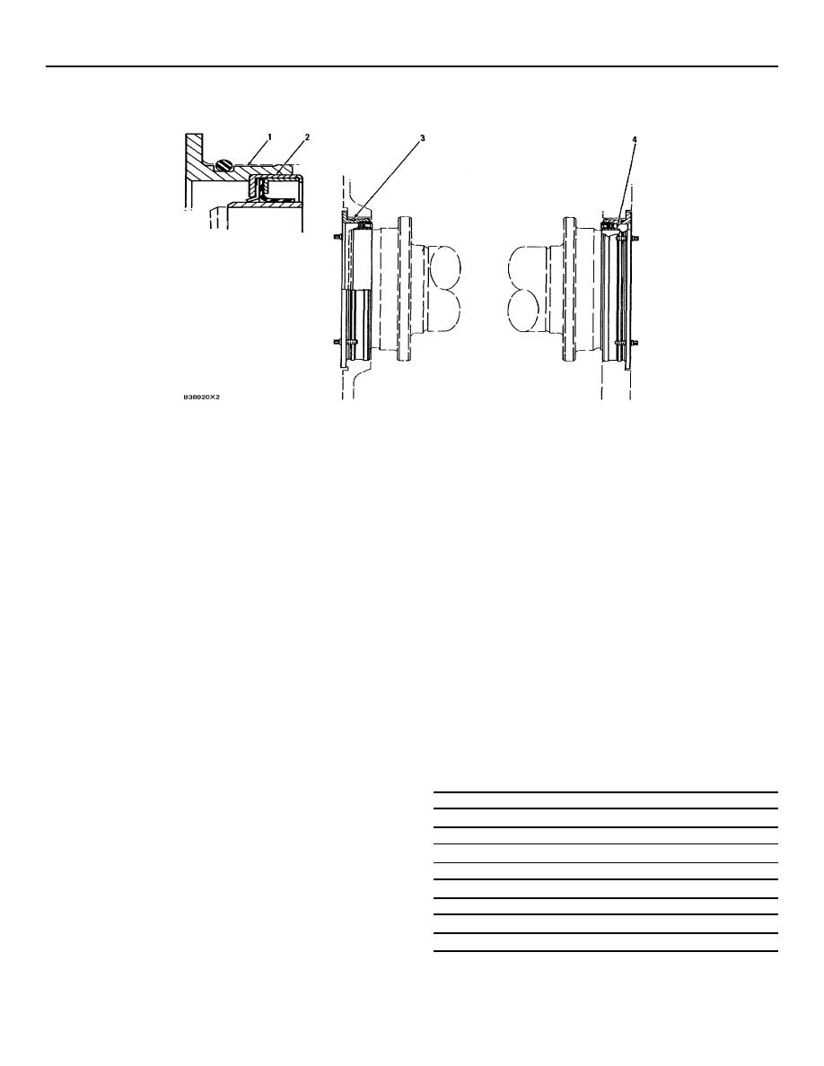
CRANKSHAFT WEAR SLEEVES
AND SEALS
(1)
Adapter.
NOTE: For complete procedure with illustrations, make
(2)
Crankshaft seals:
reference to Disassembly and Assembly section of this
Service Manual.
Crankshaft seals must be installed with the lip of
the seal toward the inside of the engine as
b.
Install sleeve and seal assembly into
shown. Make sure the correct seal is installed
adapter (1) with correct tools.
on each end of the crankshaft.
For SAE
Standard Rotation engines use 1W6974 Seal
c.
Clean the outer surface of the crankshaft
Group on the front and 1W6977 Seal Group on
and the inner surface of wear sleeve (4)
the rear. For SAE Opposite Rotation engines
with 6V1541 Quick Cure Primer.
use 1W6977 Seal Group on the front and
1W6974 Seal Group on the rear.
d.
Carefully put a thin coat of 9S3265
Retaining Compound on the inner surface
(3)
Put clean engine oil on the O-ring seals at
of wear sleeve (4) and on crankshaft
assembly.
surface.
(4)
Wear sleeve.
e.
Install adapter (1), seal (2) and wear sleeve
(4) as a unit on the end of the crankshaft
Removal:
with the correct tools.
a.
Remove the seal adapters from each end of
Tools Needed
the engine and remove the seals from the
adapters.
6V4002
Forcing Bracket
(2)
6V4001
Forcing Ring
(1)
NOTE: Seals and wear sleeves can not be used again,
1B4330
Nut (5/16"-18 NC)
(4)
after the seals and wear sleeves are separated.
6V4003
Locator
(1)
2N5006
Bolt (1"-14 NF x
(2)
b.
Remove wear sleeves with 5P7409
2 5 in. long)
Distorter and 6V3143 Distorter Adapter.
Guide Bolts (5/16"-
(2)
Installation:
18 NC x 4 in. long)
6V4977
Installer
(1)
a.
Do not separate wear sleeves (4) from
9S8858
Nut
(1)
crankshaft seals (2).
Once they are
separated, they can not be used again.
40
|
||
|
||


