
| Tweet |

Custom Search
|
|

|
||
 FUEL SYSTEM
SYSTEMS OPERATION
FUEL SYSTEM
GENERAL
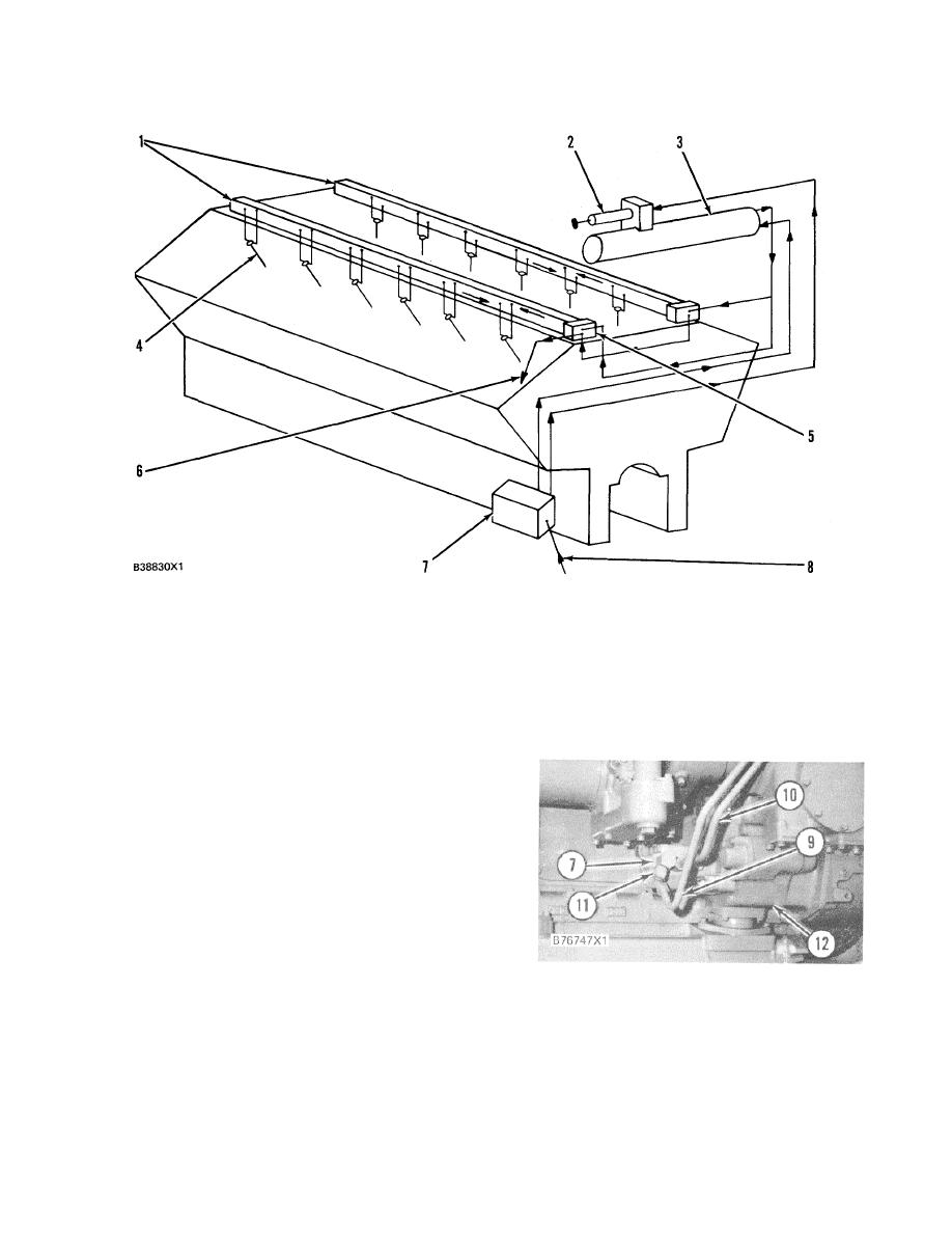
FUEL FLOW SCHEMATIC
(3512 Illustrated)
1. Fuel manifolds. 2. Fuel priming pump. 3. Fuel filter housing. 4. Fuel injectors. 5. Pressure regulating valve.
6. Fuel return to supply. 7. Fuel transfer pump. 8. Fuel from supply.
Fuel transfer pump (7) is located on the right
The transfer pump pushes fuel through fuel filter
side of the engine. The lower shaft of engine oil pump
housing (3) to fuel manifolds ( ). The fuel manifolds have
(12) drives the gear type transfer pump. Fuel from the
two sections. The fuel flows through the top section of
supply tank is pulled through a primary fuel filter by the
the manifold to inlet fuel line ( 14) connect-
transfer pump and sent to the fuel filter housing.
The transfer pump has a check valve and a
bypass valve. The check valve is located in the pump
head assembly located behind where line (9) is
connected. The check valve prevents fuel flow back
through the transfer pump when priming pump (2) is
used. The bypass valve is located behind a cap (plug) in
the drive end of the pump. The bypass valve limits the
maximum pressure of the fuel. It will open the outlet side
of the pump to the pump inlet if the fuel pressure goes
up to 860 kPa (125 psi). This helps prevent damage to
RIGHT SIDE OF ENGINE
fuel system components caused by too much pressure.
7. Fuel transfer pump. 9. Fuel line to filter housing.
10. Fuel line to priming pump. 11. Elbow (fuel
supply).
12. Engine oil pump.
65
|
||
|
||


