
| Tweet |

Custom Search
|
|

|
||
 FUEL SYSTEM
SYSTEMS OPERATION
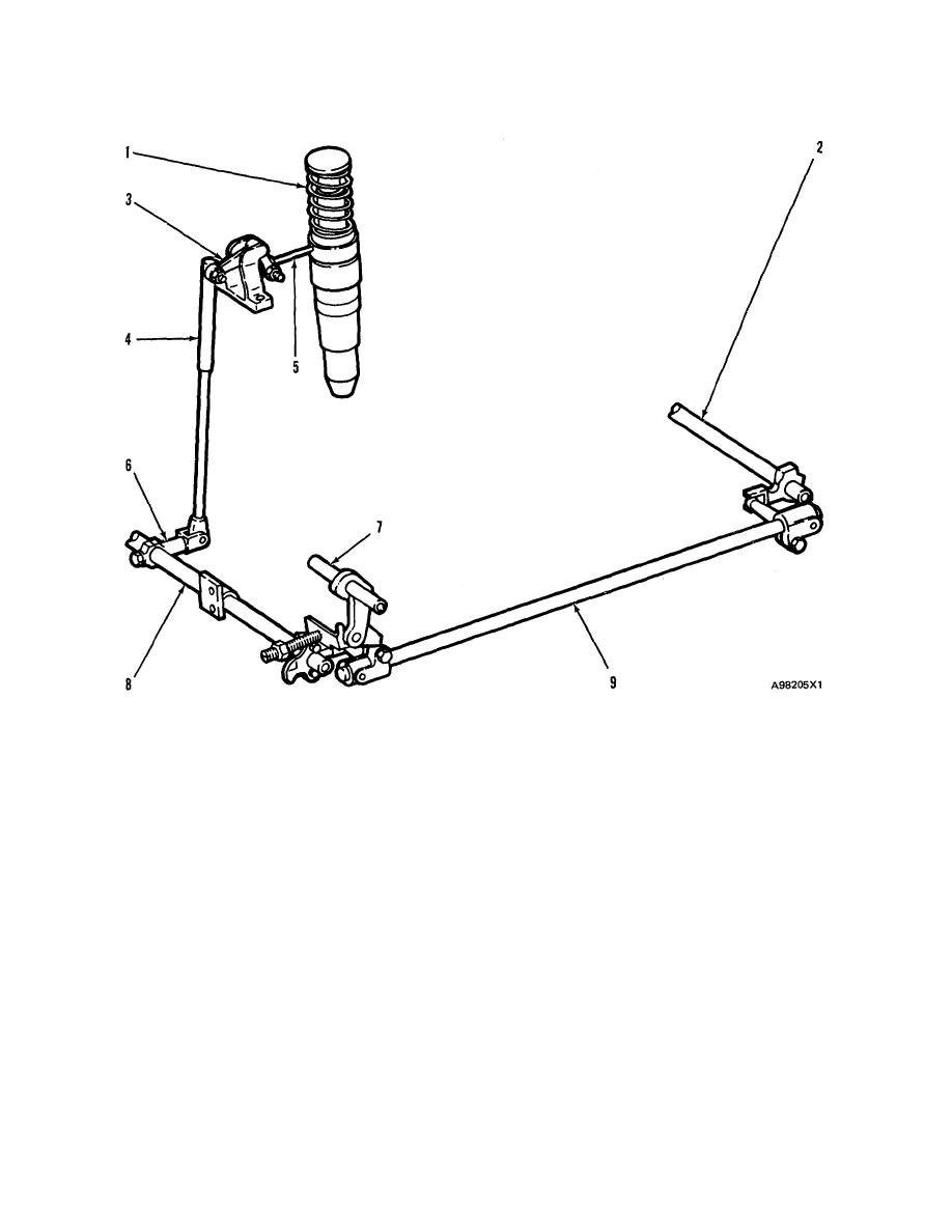
FUEL INJECTION CONTROL LINKAGE
FUEL INJECTOR CONTROL LINKAGE
1. Injector. 2. Control shaft (left side). 3. Bellcrank. 4. Control rod. 5. Rack. 6. Lever. 7. Governor shaft. 8.
Control shaft (right side}. 9. Cross shaft.
A fuel injector ( 1 ) is located in each cylinder
When the rotation of governor shaft (7) is clock-
head. The position of rack (5) controls the amount of fuel
wise, as seen from in front of the engine, the action of
injected into-the cylinder. Pull the rack out of the injector
the governor linkage moves control shaft (8) coun-
for more fuel, push it in for less fuel.
terclockwise. That is, in the fuel "ON" direction.
Right control shaft (8) and left control shaft (2)
Rack position is changed by bellcrank (3). The
bellcrank is moved by control rod (4). The control rods
are connected by cross shaft (9). The linkage between
have an adjustment screw on the top. The adjustment
the injectors on the left side of the engine and control
screw is used to synchronize the injectors. The control
shaft (2) is similar to the linkage on the right side.
rods are spring loaded. If the rack of one injector sticks
(will not move), it will still be possible for the governor to
Should the linkage become disconnected from
control the other racks so the engine can be shutdown.
the governor, the weight of the control linkage will move
Each control rod on the right side of the engine is
the fuel injector racks to the fuel "SHUTOFF" position,
connected by a lever (6) to control shaft (8).
and the engine will stop.
67
|
||
|
||


