
| Tweet |

Custom Search
|
|

|
||
 BASIC BLOCK
SYSTEMS OPERATION
BASIC BLOCK
CYLINDER BLOCK, LINERS AND HEADS
Covers (1) allow access to the camshafts, valve
lifters and fuel control shaft.
The cylinders in the left side of the block make
an angle of 600 with the cylinders in the right side of the
Covers (2) allow access to the crankshaft
block. The main bearing caps are fastened to the block
connecting rods, main bearings and piston cooling jets.
with four bolts per cap.
With covers removed, all the openings can be used for
inspection and service.
The cylinder liners can be removed for
replacement. The top surface of the block is the seat for
PISTONS, RINGS AND CONNECTING RODS
the cylinder liner flange. Engine coolant flows around the
liners to keep them cool. Three O-ring seals around the
The aluminum pistons have an iron band for the
bottom of the liner make a seal between the liner and the
top two rings.
This helps reduce wear on the
cylinder block. A filler band goes under the liner flange
compression ring grooves. A chamber is cast into the
and makes a seal between the top of the liner and the
piston just behind the top ring grooves. Oil from the
cylinder block.
piston cooling jets flows through this chamber to cool the
piston and improve ring life. The pistons have three
The engine has a separate cylinder head for
rings; two compression rings and one oil ring. All the
each cylinder. Four valves (two intake and two exhaust),
rings are located above the piston pin bore. The oil ring
controlled by a push rod valve system, are used for each
is a standard (conventional) type. Oil returns to the
cylinder. Valve guides without shoulders are pressed
crankcase through holes in the oil ring groove. The top
into the cylinder heads. The opening for the fuel injector
two rings are the KEYSTONE type, which are tapered.
is located between the four valves. A third lobe on the
The action of the ring in the piston groove, which is also
camshaft moves the push rod system that operates the
tapered, helps prevent seizure of the rings caused by too
fuel injector. Fuel is injected directly into the cylinder.
much carbon deposit.
There is an aluminum spacer plate between
The connecting rod has a taper on the pin bore
each cylinder head and the block. Coolant goes out of
end. This gives the rod and piston more strength in the
the block through the spacer plate and into the head
areas with the most load. Four bolts set at a small angle
through eight openings in each cylinder head face.
hold the rod cap to the rod. This design keeps the rod
Water seals are used in each opening to prevent coolant
width to a minimum, so that a larger rod bearing can be
leakage. Gaskets seal the oil drain passages between
used and the rod can still be removed through the liner.
the head, spacer plate and block.
CRANKSHAFT
The crankshaft changes the combustion forces
in the cylinder into usable rotating torque which powers
the machine. A vibration damper of the fluid type is used
at the front of the crankshaft to reduce torsional
vibrations (twist on the crankshaft) that can cause
damage to the engine.
The crankshaft is symmetrical. This makes it
possible to turn the crankshaft end for end when opposite
engine rotation is desired.
The crankshaft drives a group of gears on the
front and rear of the engine. The gear group on the front
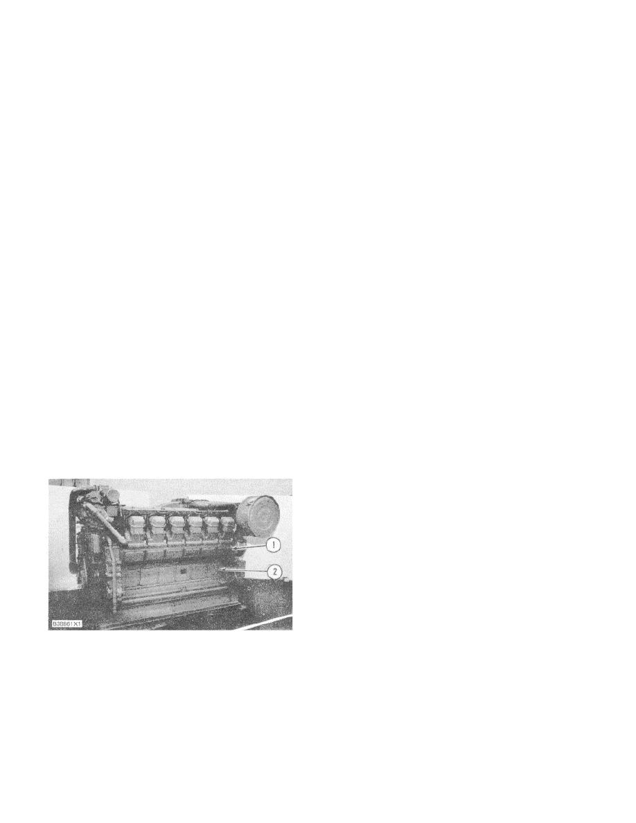
LEFT SIDE OF 3512 ENGINE
of the engine drives the oil pump, water pump, fuel
1. Covers for camshafts and fuel control linkage
transfer pump, governor and two accessory drives. The
Inspection. 2. Covers for crankshaft main and rod
gear group on the rear of the engine drives the
bearing inspection.
camshafts.
84
|
||
|
||


