
| Tweet |

Custom Search
|
|

|
||
 FUEL SYSTEM
TESTING AND ADJUSTING
1.
Handle (4) must be in an upright position as
shown. Use control lever (12) to extend rocker
arm (10), then pull injector rack (27) all the way
out. Use switch (11 ) to turn on the panel light.
Open test pressure valve (9) a minimum of one
complete turn.
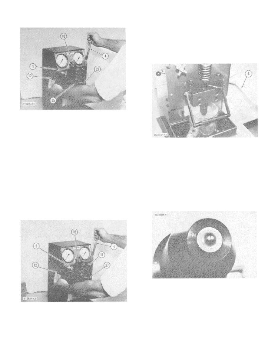
AIR REMOVAL FROM INJECTOR
1. Sight tube. 4. Handle. 10. Rocker arm. 12.
Rocker arm control lever. 25. Injector. 27. Injector
rack.
11.
Release handle (4) and let it come back to the
INJECTOR UNDER TEST
upright position. Move control lever (12) to
4. Handle.
retract rocker arm (10). Again use handle (4) to
pump test fluid through the tester, for 10 or 12
strokes, and look for air bubbles at sight gauge
2.
The injector tip shown has nine orifices.
(1). When no air bubbles can be seen at sight
Numbers on the tip of the injector will show:
gauge ( I ), the injector is ready for the test
number of orifices, size of the orifices, and spray
procedure. If air bubbles are seen at sight
angle of orifices. An explanation of the 9-0.254-
gauge (1), do Steps 8 through 11 again until all
160 as shown in illustration is as follows: nine
air is removed from the tester system.
0.254 mm orifices that have a 1600 spray angle.
According to engine model and/or application,
NOTE: Injector rack (27) must be pulled out all the way
these numbers or specifications can be different
for all tests.
from engine to engine.
II. Orifice Inspection
INJECTOR TIP
3.
Use handle (4) to pump the tester just fast
enough to make sure orifices are not plugged.
INJECTOR IN POSITION FOR TEST
4. Handle. 9. Test pressure valve. 10. Rocker arm.
11. Light switch. 12. Rocker arm control lever. 27.
Injector rack.
112
|
||
|
||


