
| Tweet |

Custom Search
|
|

|
||
 FUEL SYSTEM
TESTING AND ADJUSTING
timing pins (2) from their storage positions.
CAMSHAFT TIMING
Timing Check
5.
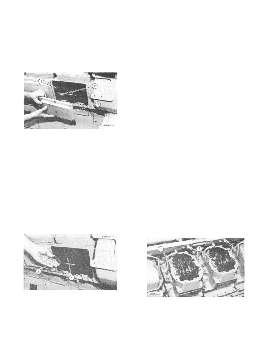
Install timing pins (2) through holes (1) in the
engine block and into the groove (slot) in
Tools Needed:
camshaft (4) on each side of the engine. For the
9S9082 Engine Turning Tool.
engine to be timed correctly, the timing pins
must fit into the groove of each camshaft.
1.
Remove rear camshaft cover (3) from both sides
of the engine.
6.
If timing pins (2) do not engage in the grooves of
both camshafts, the engine is not in time, and
one or both camshafts must be adjusted.
7.
Both camshafts are adjusted the same way.
See TIMING ADJUSTMENT for the procedure to
put the camshafts in time with the crankshaft.
NOTICE
If a camshaft is out of time more than 18 degrees
(approximately 1/2 the diameter of timing pin out of
groove), the valves can make contact with the
pistons. This will cause damage that will make
1. Timing hole. 2. Timing pin. 3. Cover.
engine repair necessary.
2.
Make reference to FINDING TOP CENTER
Timing Adjustment
POSITION FOR NO. I PISTON.
Tools Needed:
NOTE: Since both rear camshaft covers have to be
9S9082 Engine Turning Tool.
removed to check the timing, it is not necessary to
6V3010 Puller Group.
remove No. 1 valve cover to find the compression stroke
9S9089 Two 1/2 - 13 NC Bolts 114.3 mm (4.50
when timing bolt is installed in flywheel.
in.) long.
5P1076 Two Washers (Hardened).
3.
With timing bolt installed in flywheel, look at rear
of camshaft to see if timing groove (slot) is
NOTE: Before any timing adjustments are made, the
visible on the camshaft. If it is visible, No. 1
timing must be checked first to see if adjustment is
piston is on the compression stroke. If it is not
necessary.
See subject TIMING CHECK for this
visible, feel the backside of the camshaft for the
procedure.
groove. If the groove is at the back of the
camshaft, the flywheel will have to be turned
After TIMING CHECK procedure is complete,
3600 to put No. 1 piston on the compression
timing bolt will be engaged in flywheel with No. 1 piston
stroke.
at top center (TC) position.
INSTALLATION OF TIMING PINS
LOOSEN ROCKER SHAFTS
2. Timing pin. 4. Camshaft (L.H.).
1. Bolt. 2. Rocker shaft.
4.
With timing bolt installed in flywheel with No. 1
piston now on compression stroke, remove
118
|
||
|
||


