
| Tweet |

Custom Search
|
|

|
||
 FUEL SYSTEM
TESTING AND ADJUSTING
Fuel Setting Check
Fuel setting is the adjustment of the fuel setting
screw to a specified position. The fuel setting screw
limits the power output of the engine by setting the
maximum travel of all the injector racks.
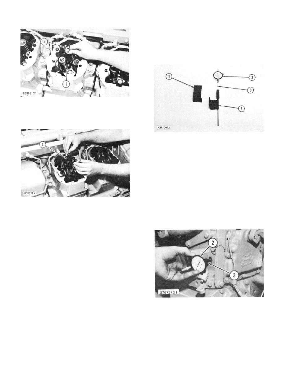
GAUGE IN POSITION ON INJECTOR RACK
(Rocker Shaft Removed for Illustration)
5. 6V3119 Rack Synchronizing Gauge [12.7 mm (.50
in.)]. 7. Fuel injector rack.
SYNCHRONIZATION AND FUEL SETTING TOOLS
1. 6V3119 Rack Synchronizing Gauge. 2. 6V3075
Dial Indicator (metric). 3. 5P4814 Collet. 4. 5P7263
Contact Point, 76.2 mm (3.00 in.) long.
Before the fuel setting is checked, the injectors must be
correctly synchronized. See the subject INJECTOR
SYNCHRONIZATION.
After the injectors are
synchronized correctly, leave the synchronizing pin in
place for the procedure that follows.
1.
Put 6V3075 Dial Indicator (2) with 5P7263
Contact Point (4) in 5P4814 Collet (3). Remove
ADJUSTMENT OF FUEL CONTROL ROD
the plug from the right side of fuel setting cover
5. 6V3119 Rack Synchronizing Gauge.
(8).
6.
Use rack synchronizing gauge (5) and, if
necessary, make the adjustment to the other
injectors, When all adjustments have been
made, release the actuator terminal shaft.
7.
Install the valve covers.
8.
Make a check of the fuel setting and make
adjustments if necessary. See FUEL SETTING
AND RELATED INFORMATION FICHE for this
procedure.
FUEL SETTING
Tools Needed:
6V3139 Timing and Fuel Setting Tool Group.
5P4814 Collet.
INSTALL DIAL INDICATOR
6V3075 Dial Indicator (metric).
5P7263 Contact Point, 76.2 mm (3.00 in.) long.
2. 6V3075 Dial Indicator with 5P7263 Contact Point
6V3119 Rack Synchronizing Gauge 12.7 mm (.50
attached. 3. 5P4814 Collet.
in.).
125
|
||
|
||


