
| Tweet |

Custom Search
|
|

|
||
 BASIC BLOCK
TESTING AND ADJUSTING
The crankshaft deflection must be checked after
4. 4. Turn the crankshaft in the direction of normal
the final installation of the engine. The check must be
rotation until the indicator almost makes contact with
made with the engine cold and also with the engine at
the connecting rod on the other side of the
the temperature of normal operation. The procedure that
crankshaft.
follows can be used to check crankshaft deflection with
the engine either cold or warm.
NOTE: Do not let the indicator make contact with the
connecting rod.
1.
Remove an inspection cover from the cylinder
block that will give access to the connecting rod
5.
The dial indicator reading must not change more
journal of the crankshaft nearest to the center of
than 0.03 mm (.001 in.) for the approximately
the engine.
300 degrees of crankshaft rotation. Now turn the
crankshaft in the opposite direction to the
2.
Turn the crankshaft in the direction of normal
starting position. The dial indicator must now
rotation until the center of the counterweights
read zero. If the dial indicator does not read
just go beyond the connecting rod.
zero, do the procedure again.
If the dial indicator reads more than 0.03 mm
(.001 in.), the cylinder block is bent. Loosen the bolts
that hold the engine mounting rails to the foundation
mounting rails and adjust the shims to make the engine
straight again. Also check to see if the engine mounting
bolts have enough clearance to let the engine have
expansion as it gets hot.
VIBRATION DAMPER
Damage to or failure of the damper will increase
vibrations and result in damage of the crankshaft.
If the damper is bent or damaged, or if the bolt
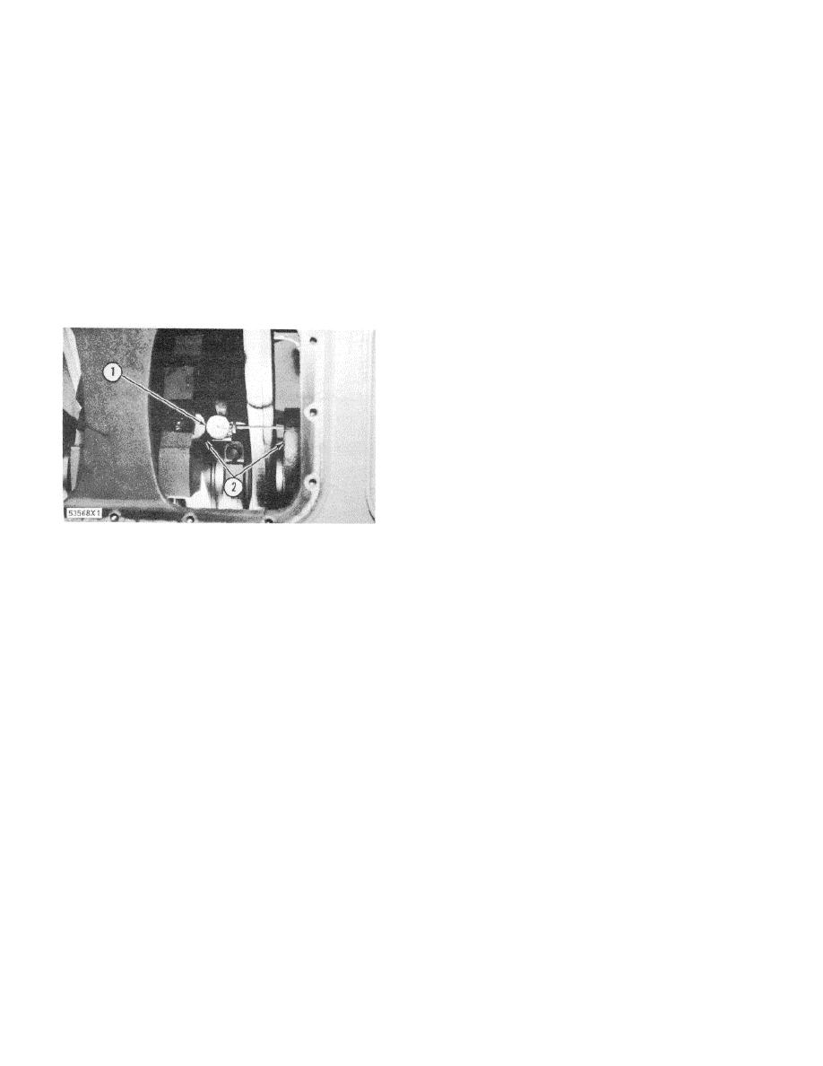
MEASURING DEFLECTION OF THE CRANKSHAFT
holes in the damper are loose fitting, replace the damper.
(TYPICAL EXAMPLE)
Replacement of the damper is also needed at the time of
1. Dial gauge. 2. Mounting face.
crankshaft failure (if a torsional type).
3. Install a Starrett Crankshaft Distortion Dial Gauge
No.
696 with Starrett No.
696B Balancer
Attachment between the counterweights as shown.
Put dial gauge (1) within 6.4 mm (.25 in.) of
counterweight mounting surface (2). Turn the dial of
the indicator to get alignment of the zero and the
pointer. Turn the indicator on its end points until the
pointer of the indicator will not move from zero.
149
|
||
|
||


