
| Tweet |

Custom Search
|
|

|
||
 ELECTRICAL SYSTEM
TESTING AND ADJUSTING
The solenoid operation also closes the electric
circuit to the motor. Connect one lead of the multimeter
to the solenoid connection (terminal) that is fastened to
the motor. Put the other lead to a good ground. Activate
the starter solenoid and look at the multimeter. A
reading of battery voltage shows the problem is in the
motor. The motor must be removed for further testing.
A zero reading on the multimeter shows that the solenoid
contacts do not close. This is an indication of the need
for repair to the solenoid or an adjustment to be made to
the starter pinion clearance.
Make a test with one multimeter lead fastened to
the connection (terminal) for the small wire at the
solenoid and the other lead to the ground. Look at the
multimeter and activate the starter solenoid. A voltage
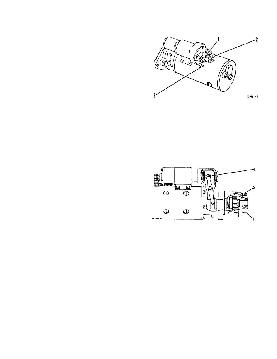
CONNECTION FOR CHECKING PINION CLEARANCE
reading shows that the problem is in the solenoid. A zero
1. Connector from MOTOR terminal on solenoid to
reading is an indication that the problem is in the start
motor. 2. SW terminal. 3. Ground terminal.
switch or the wires for the start switch.
4.
Connect for a moment, a wire from the solenoid
Fasten one multimeter lead to the start switch at
connection (terminal) marked MOTOR to the
the connection (terminal) for the wire from the battery.
ground connection (terminal). The pinion will
Fasten the other lead to a good ground. A zero reading
shift to crank position and will stay there until the
indicates a broken circuit from the battery. Make a check
battery is disconnected.
of the circuit breaker and wiring. If there is a voltage
reading, the problem is in the start switch or in the wires
for the start switch.
A starter motor that operates too slow can have
an overload because of too much friction in the engine
being started. Slow operation of the starter motor can
also be caused by a short circuit, loose connections
and/or dirt in the motor.
Pinion Clearance Adjustment
When -the solenoid is installed, make an
adjustment of the pinion clearance. The adjustment can
PINION CLEARANCE ADJUSTMENT
be made with the starter motor removed.
4. Shaft nut. 5. Pinion. 6. Pinion clearance.
1.
Install the solenoid without connector (1) from
5.
Push the pinion toward the commutator end to
the MOTOR connections (terminal) on solenoid
remove free movement.
to the motor.
6.
Pinion clearance (6) must be 8.4 to 9.9 mm (.33
2.
Connect a battery, of the same voltage as the
to .39 in.).
solenoid, to the terminal (2), marked SW.
7.
To adjust pinion clearance, remove plug and turn
3.
Connect the other side of the battery to ground
nut (4).
terminal (3).
153/(154 Blank)
|
||
|
||


