
| Tweet |

Custom Search
|
|

|
||
 3161 GOVERNOR
SYSTEMS OPERATION
AUXILIARY CONTROLS
This section describes the Auxiliary Controls and
let control oil drain and cause engine shutdown.
attachments that are available for the 3161 Governor.
The manual shutdown can be used in addition to
These controls are installed and calibrated at the factory
the pressure or electric shutdown controls.
before shipment to the user. The shutdown controls can
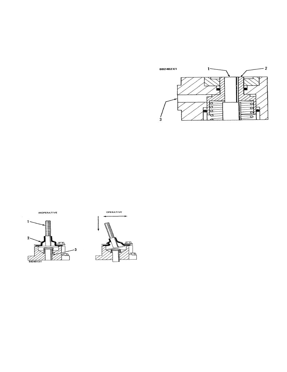
PRESSURE SHUTDOWN
be added to a governor already in service without any
further modification to the governor.
The controls that can be fastened to the
governor top cover are:
1.
Manual Shutdown
2.
Mechanical Shutdown
3.
Electric Shutdown
PRESSURE SHUTDOWN
4.
Pneumatic Speed Setting Control
1. Shutdown plunger. 2. Shutdown piston. 3.
Shutdown control pressure passage.
5.
Air Fuel Ratio Control
The pressure shutdown assembly is installed on
Other controls added to the governor include:
the right front cover of the governor top cover.
1.
Speed Adjusting Motor Head
This shutdown uses either pneumatic or
hydraulic pressure at a minimum of 276 kPa (40 psi) to
2.
Manual Speed Setting Control
shutdown the engine. When the pressure (air or oil) is
applied to the shutdown piston, the piston is moved down
3.
Manual Mechanical Speed Control
and makes contact with the shutdowns plunger. The
plunger then pushes down on the shutdown rod and the
4.
Pneumatic Mid Speed Control
shutdown/limit pilot valve. The pilot valve then lets
control oil drain from under the power piston and causes
MANUAL SHUTDOWN
engine shutdown.
The shutdown will reset when
pressure goes below 138 kPa (20 psi) and lower.
The pressure shutdown can be used in addition
to the manual or electric shutdown controls. If this
shutdown is added after the governor has been shipped
from the factory, and is not used with any other
shutdown, a small cover and gasket must be installed on
top of the shutdown assembly.
ELECTRIC SHUTDOWN
MANUAL SHUTDOWN
The electric shutdown assembly (1) is installed
on the right front corner of the governor top cover. This
1. Threaded shutdown handle. 2. Boot. 3. Shutdown
shutdown uses a 24 volt DC (energized-to-shutdown)
plunger.
solenoid that positions the shutdown lever and
shutdown/limit pilot valve.
When the solenoid is
The manual shutdown assembly is installed on
energized the plunger moves down. It lowers the
the right front corner of the governor top cover.
shutdown rod and shutdown/limit pilot valve to let control
oil drain from under the power piston and cause engine
To shutdown the engine, the threaded shutdown
shutdown.
handle can be either pushed down or tilted in any one of
the 360 degrees to make contact with the shutdown rod.
As the shutdown handle is tilted, the flat disc of the
shutdown handle lowers the shutdown/limit pilot valve, to
164
|
||
|
||


