
| Tweet |

Custom Search
|
|

|
||
 3161 GOVERNOR
SYSTEMS OPERATION
NOTE: If the speed adjusting motor has been allowed to
SPEED ADJUSTING MOTOR GOVERNOR HEAD
run after the low speed setting has been reached, it may
take a period of time for the speed adjusting screw to
turn in and make contact with the speed adjusting lever
(when an increase in speed setting is required).
All wiring and power to the remote speed setting
motor on the governor must be low voltage DC. A
converter drop box which will convert 115 or 230 volt AC
(50 to 60 Hertz) to 24 volt DC is available (2W4523).
This box should be remote mounted from the engine to
isolate the engine wiring harness from high voltage AC
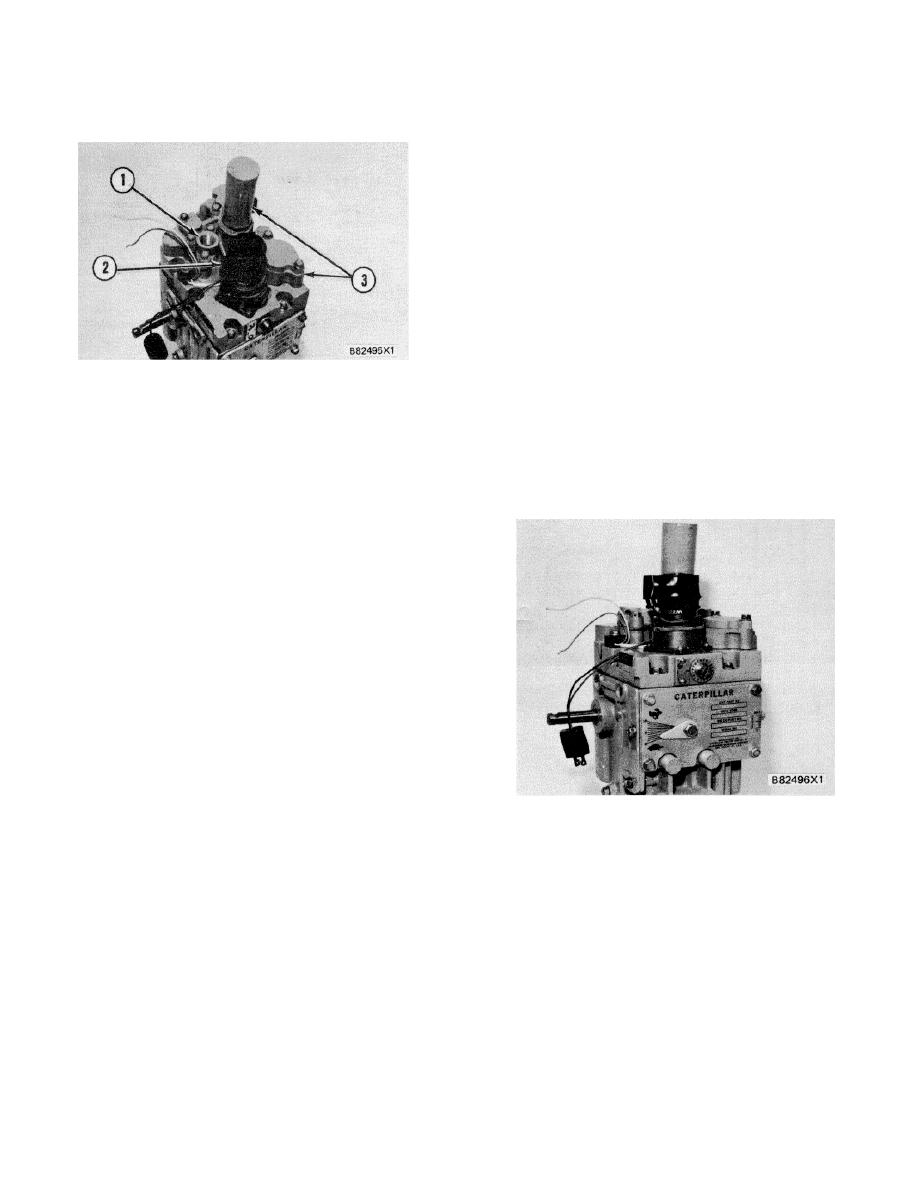
An internal one-half inch thread conduit
connection (1) is on top of the governor cover. It is used
3161 GENERATOR SET GOVERNOR
for installations which require conduit protection for the
1. Conduit connection. 2. Speed adjusting meter.
wiring.
3. Electric shutdown assembly.
The top governor cover is made for installation of
The speed adjusting motor governor head
any of the three shutdown assemblies.
includes a 24/32 Volt DC remote control speed adjusting
motor (2) for changing engine speeds from remote
MANUAL SPEED SETTING CONTROL
locations. The speed adjusting motor is installed on the
governor top cover and is connected to the governor
speed setting mechanism through a friction clutch. The
motor drives through the friction clutch and rotates the
speed adjusting screw to position the governor's speed
adjusting lever.
The governor set speed may be
increased or decreased at the rate of 13 rpm/ second.
One revolution of the manual adjusting screw will
increase engine speed 63 rpm (approximately).
To increase the speed setting, the motor shaft
rotates clockwise. As the motor shaft rotates, it turns the
speed adjusting screw to make contact with the speed
adjusting lever and lowers it to increase the governor's
speed setting. The motor shaft turns the speed adjusting
screw until the speed adjusting lever contacts the high
speed stop. If the motor continues to run, the clutch will
slip to prevent damage to the motor.
3161 GENERATOR SET GOVERNOR
NOTICE
The motor should not be left running with the clutch
The manual speed setting control is located on
slipping, or clutch wear will occur. To decrease
the front of the speed adjusting motor governor head.
speed
setting,
the
motor
shaft
turns
Engine speed is set manually as the speed setting screw
counterclockwise and the speed adjusting screw
is turned. The high and low idle stops limit the speed
backs out, allowing the speed adjusting lever to
range.
move to the "decrease speed" setting.
If the motor shaft is permitted to rotate
counterclockwise after the speed adjusting lever has
reached the low speed stop screw, the speed
adjusting screw will turn out to the maximum
position. The clutch will then slip until the motor is
stopped.
169
|
||
|
||


