
| Tweet |

Custom Search
|
|

|
||
 3161 GOVERNOR
SYSTEMS OPERATION
.70 SYSTEMS OPERATION The manual mechanical
speed control with remote and positive lock is available
for torque rise and non-torque rise equipped governors.
The control is used for manually setting different ~,_
engine speeds, or it can be used as a remote speed
control.
The shaft (1) goes through the handle assembly (2) and
is threaded into the hub (4) on the spline of the speed
setting shaft. The guide (3) rotates on the speed setting
shaft and supports the handle assembly. The ratchet
mounting plate (6) is bolted to the front of the governor
and has notches to hold the handle for different engine
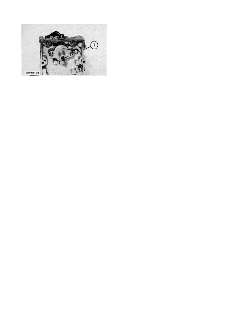
TOP COVER OF THE 3161 GENERATOR SET
speeds. The quadrant (5) can be engaged with the
GOVERNOR
handle assembly and used as a mechanical linkage to
1. Speed adjusting screw.
the speed setting shaft.
An indicator lever is attached to the governor
A cable or rod can be connected to the quadrant and
speed setting shaft with a bolt. The bolt can be loosened
used for remote speed control.
and the indicator lever can be set to the reference points
on the identification and information plate to correspond
To increase or decrease engine speed, push on the shaft
with the number on the dial. The indicator lever will show
and lift on the handle assembly. This disengages the
the speed setting before the engine is started.
handle assembly from the ratchet mounting plate. The
control can then move the speed setting shaft.
The manual speed setting control and the speed
Movement of the handle in the clockwise direction
adjusting motor use a common speed adjusting screw
increases the engine speed.
which contacts the governor speed adjusting lever.
To disengage the handle assembly from the ratchet and
The speed adjusting motor clutch is above the
connect the quadrant, push on the shaft and lift on the
gear and connects the motor to the speed adjusting
handle assembly. With the handle assembly raised, turn
screw. This clutch keeps force off of the speed adjusting
it 180 degrees and connect it to the quadrant. The
motor as the speed setting is adjusted manually.
control can now be used for remote operation.
MANUAL MECHANICAL SPEED CONTROL
NOTE
: The manual mechanical speed control with remote and
3161 GOVERNOR 1. Shaft. 2. Handle assembly. 3.
positive lock should not be used with a pneumatic speed
Guide. 4. Hub. 5.
control. Vibration can cause the manual mechanical
speed control to engage and stop pneumatic speed
Quadrant. 6. Ratchet mounting plate.
control operation.
PNEUMATIC MID SPEED CONTROL A pneumatic
speed control is normally used on 3161 Governors on
vehicular engine arrangements to control the engine
speed. A pneumatic mid speed control is also used to
make the engine go from low idle to mid speed for
dynamic braking with the direct current generator and
drive motors.
This control is installed on the front of the governor.
With a lever fastened to the speed setting " control shaft,
the control cylinder sets the engine speed from low idle
to mid speed. The mid speed setting of the governor is
set by the position the control lever is fastened to the
speed setting control shaft.
170
|
||
|
||


