
| Tweet |

Custom Search
|
|

|
||
 3161 GOVERNOR
TESTING AND ADJUSTING
There are two control levers for the 3161
Governor used on 3500 Series Engines. Lever (3) has a
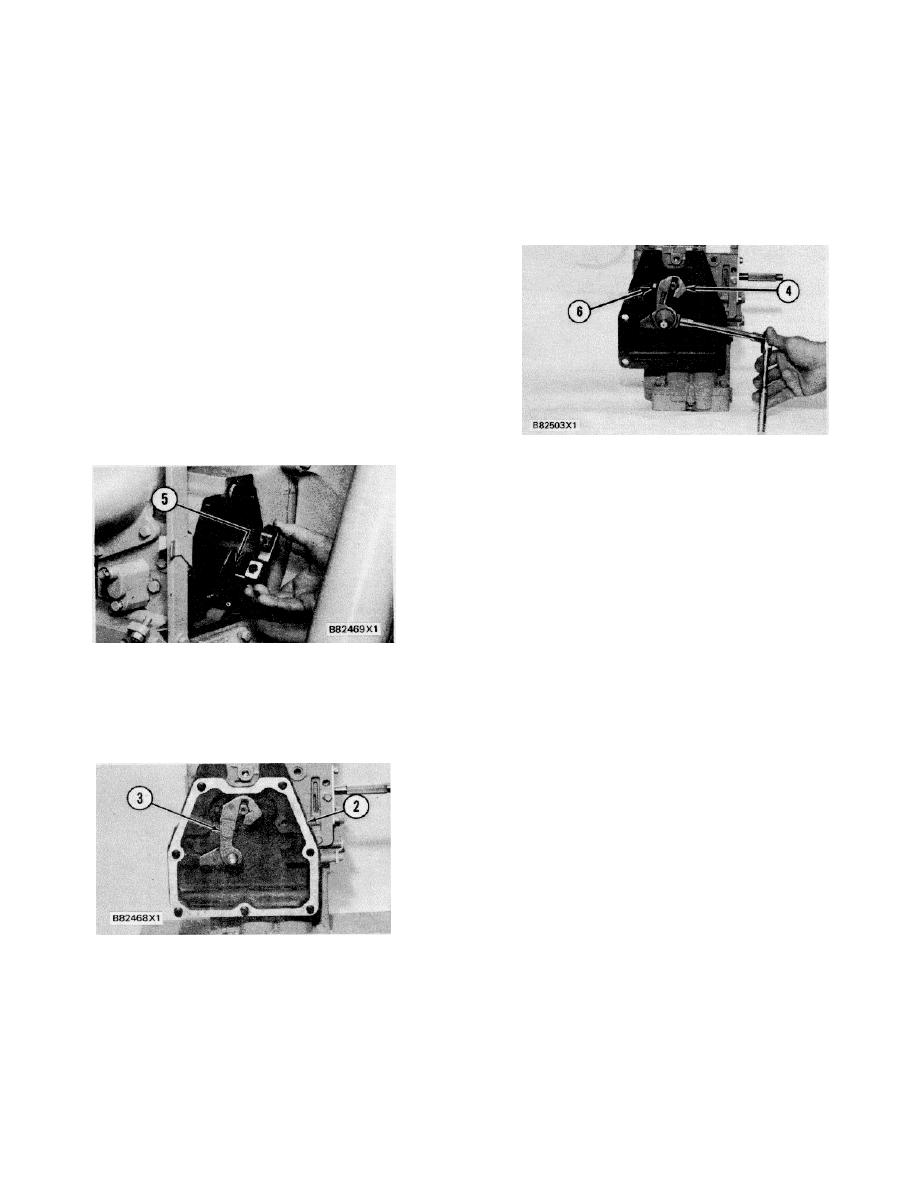
After fuel control linkage cover (2) is in position,
fixed pin and lever (4) has an adjustable pin. The fixed
install lever (3) on the governor terminal shaft and tighten
the bolt to a torque of 25 7 N-m (18 5 lb. ft.). Control
pin lever (3) is used on the 3161 Standard and Generator
Set Governors.
levers will go on only the correct way because of the flat
and groove of the terminal shaft and the lever pin. This
The adjustable pin lever (4) is used on 3161
control lever is for right-hand mounted governors. On
Governors with torque rise. Lever (4) is used to
control levers for left-hand mounted governors, the pin is
synchronize governor torque rise set point (balance
reversed.
point) position to engine fuel setting position.
The adjustable pin lever (4) can be used on a
right hand or left hand mounted governor. To convert
the lever from right hand governor use to left hand
governor use, remove the lock bolt and lock from the
adjustable pin. Remove the adjustable pin from the
lever, turn it around and install it into the lever the
opposite way. Install the lock and bolt into the adjustable
pin and tighten just enough to hold it in place. The lever
can now be used on the other end of the terminal shaft
for left hand mounted governors.
INSTALL LEVER
4. Lever. 6. Bolt.
For 3161 Governors with torque rise, the
adjustable pin control lever is installed on the terminal_
shaft. Bolt (6) is then tightened to a torque of 25 7 N m
o
(18 5 lb. ft.).
Before the governor is installed on the engine,
tighten the pin lock bolt enough to hold the pin in position
when the governor is installed on an engine.
ALIGNMENT OF CONTROL LEVER
After the governor is installed on an engine, the
5. Notch in fuel control linkage stop lever.
adjustable pin is turned to synchronize the governor
travel to the fuel control linkage.
See Governor
The lever and pin (fixed or adjustable) connect
Installation for the correct adjustment and setting of
the governor terminal shaft to the fuel control linkage
these governors.
stop lever. The lever pin moves in notch (5) of the stop
lever, this causes the two to move together.
NOTICE
Before the governor is installed on an engine, make
sure the pin of adjustable control lever (4) is at the
bottom of the lever as shown. if the pin is not in this
position, the control lever can bind or become
disconnected from the engine fuel control linkage.
Engine overspeed can be the result.
GOVERNOR INSTALLATION
INSTALL LEVER
NOTICE
2. Cover. 3. Lever.
To prevent damage to the governor, do not drop the
The 3161 Standard and Generator Set
governor or set it on the drive shaft, terminal shaft or
Governors with fixed pin levers do not require any
speed adjusting shaft.
special adjustments or setting when installed on the
engine.
182
|
||
|
||


