
| Tweet |

Custom Search
|
|

|
||
 3161 GOVERNOR
TESTING AND ADJUSTING
4.
Use FT1819 Governor Torque Arm Tool (4) to
move and hold the governor terminal shaft in the
"FUEL ON" direction. This puts the fuel control
linkage stop lever against the end of
synchronizing pin (1). The FT1819 Governor
Torque Arm Tool is to be attached only with the
engine shut down.
can be used to move the terminal shaft in the "FUEL ON"
direction. Hold the governor terminal shaft and fuel
control linkage against the synchronizing pin with 10 N-m
(90 lb. in.) force to give an accurate dial indicator setting.
ENGAGE GOVERNOR ZEROING PIN
9.
The zeroing pin is engaged to hold the governor
at a fixed position for setting the adjustable pin
lever to synchronize the governor travel with the
engine fuel control linkage travel. This pin is to
be engaged only with the engine shut down.
Put a 5/32 inch hex wrench in the governor
zeroing pin, push in and turn it counterclockwise
until the roll pin locks squarely behind the
bracket.
10.
Install FT1819 Governor Torque Arm Tool (4)
again to turn and hold the governor terminal
shaft and linkage against the zeroing pin.
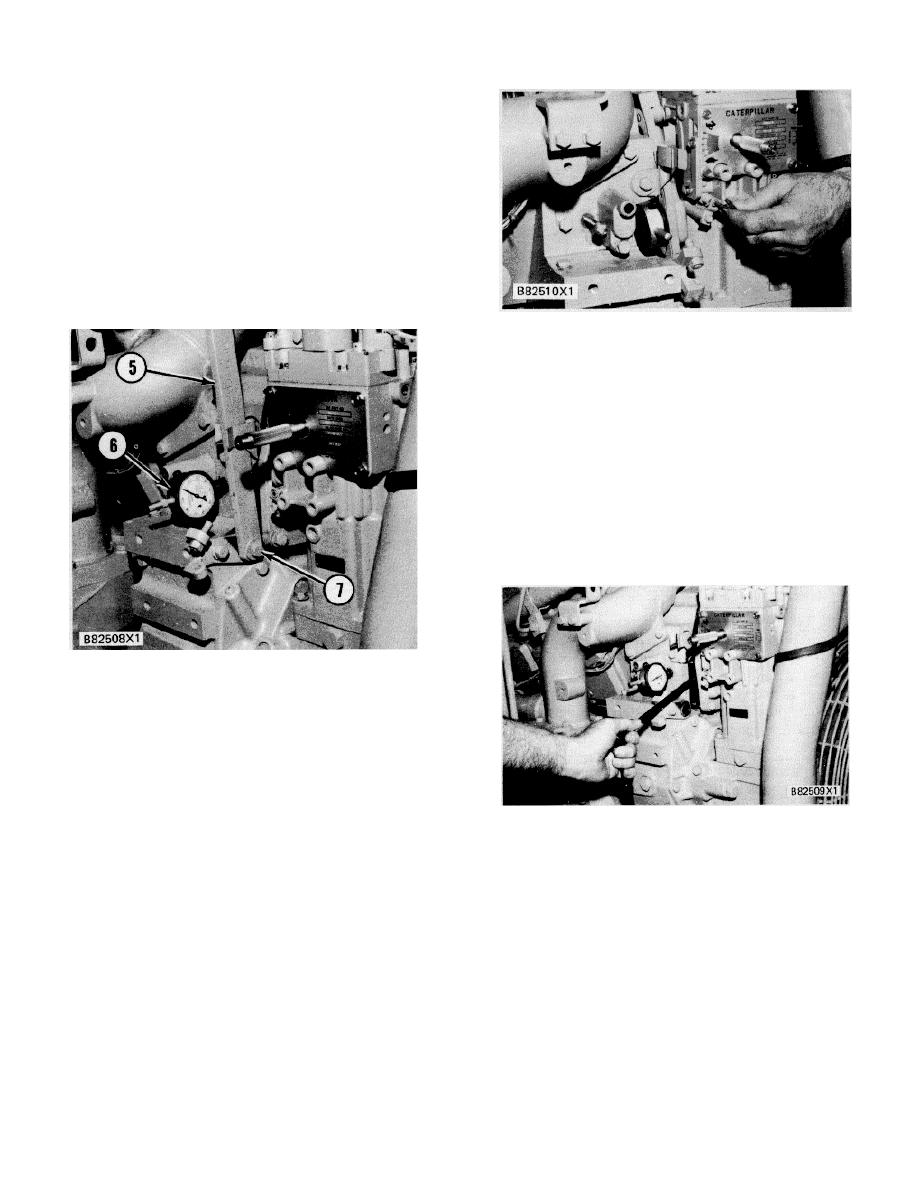
INSTALL DIAL INDICATOR
5. Manual fuel shutoff lever. 6. 6V3075 Dial
Indicator with the 5P7263 Contact Point in the
5P4814 Collet. 7. Bolt.
5.
Put 6V3075 Dial Indicator (6) with the 5P7263
Contact Point in the 5P4814 Collet. Install the
dial indicator and collet in the threaded hole as
shown. When the contact point seats against
ADJ USTABLE PIN SETTING
the fuel stop lever, slide the dial indicator in or
out until the indicator reads zero. Now tighten
the collet just enough to hold indicator at this
11.
With a 1/2 in. by 3/8 in. drive socket on a 12 in.
position.
extension and ratchet put the socket and
extension between the cover and housing. Put
6.
Remove tool (4) from the governor terminal
the socket on the bolt that holds the adjustable
shaft. Make sure the terminal shaft returns to
pin lock and loosen the bolt.
the "FUEL OFF" position.
7.
Remove bolt (7) and manual fuel shutoff lever
NOTE: Later pins use a hex socket head bolt for
(5).
use with 3/ 8in. drive sockets with a 12/4 in. hex
bit.
8.
Turn synchronizing pin (l) back out a minimum of
25 mm (I in.) or remove it completely.
Move the ratchet and extension up or down until
the dial indicator reads zero Put 0.13 mm while
the terminal shaft is held in the "FUEL ON"
direction against the governor zeroing pin.
185
|
||
|
||


