
| Tweet |

Custom Search
|
|

|
||
 3161 GOVERNOR
TESTING AND ADJUSTING
TORQUE RISE CAM ADJUSTMENT
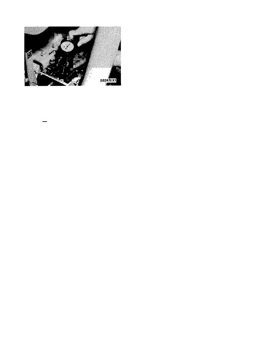
16.
Check the cam position by lifting and lowering
governor torque arm tool (4) on the terminal
shaft. The dial indicator (9) should return to the
1.00 + 0.05 mm setting. If it does not, repeat
the adjustment procedure and check again.
The following is an example of this torque rise cam
setting. If the engine were running at a rated 1800 r/min
with a load, the fuel control linkage would be at full load
position and the torque rise cam follower would have
lifted 1.00 mm. Torque rise would not have occurred, but
would be at the starting point. Should more load be
added, the engine speed would decrease. As the speed
drops, the terminal shaft and torque rise cam will move
and lift the torque rise pilot valve lever beyond the 1.00 +
0.05 mm set point. This will lift the pilot valve and
provide additional fuel to the engine and give torque rise
greater than the natural torque rise of the engine.
As more load is applied, engine speed will decrease.
The fuel control linkage will continue to move in the
"FUEL ON" direction, increasing the fuel rate until the
fuel control linkage stop lever contacts the fuel setting
screw. This is the torque rise fuel setting, and is
maximum travel.
17.
With the torque rise cam setting made, remove
the dial indicator and bracket assembly and
install the gasket and top cover on the governor.
NOTE: Make sure the air fuel ratio control limit lever is
engaged correctly in the notch of the governor housing
before the top cover is installed.
18.
Remove dial indicator (5) and the collet.
Remove synchronizing pin (1) and install it with
the washer to hold the fuel setting cover.
19.
Install the two plugs on each side of the fuel
setting cover.
191
|
||
|
||


