
| Tweet |

Custom Search
|
|

|
||
 3161 GOVERNOR
TESTING AND ADJUSTING
AUXILIARY CONTROLS
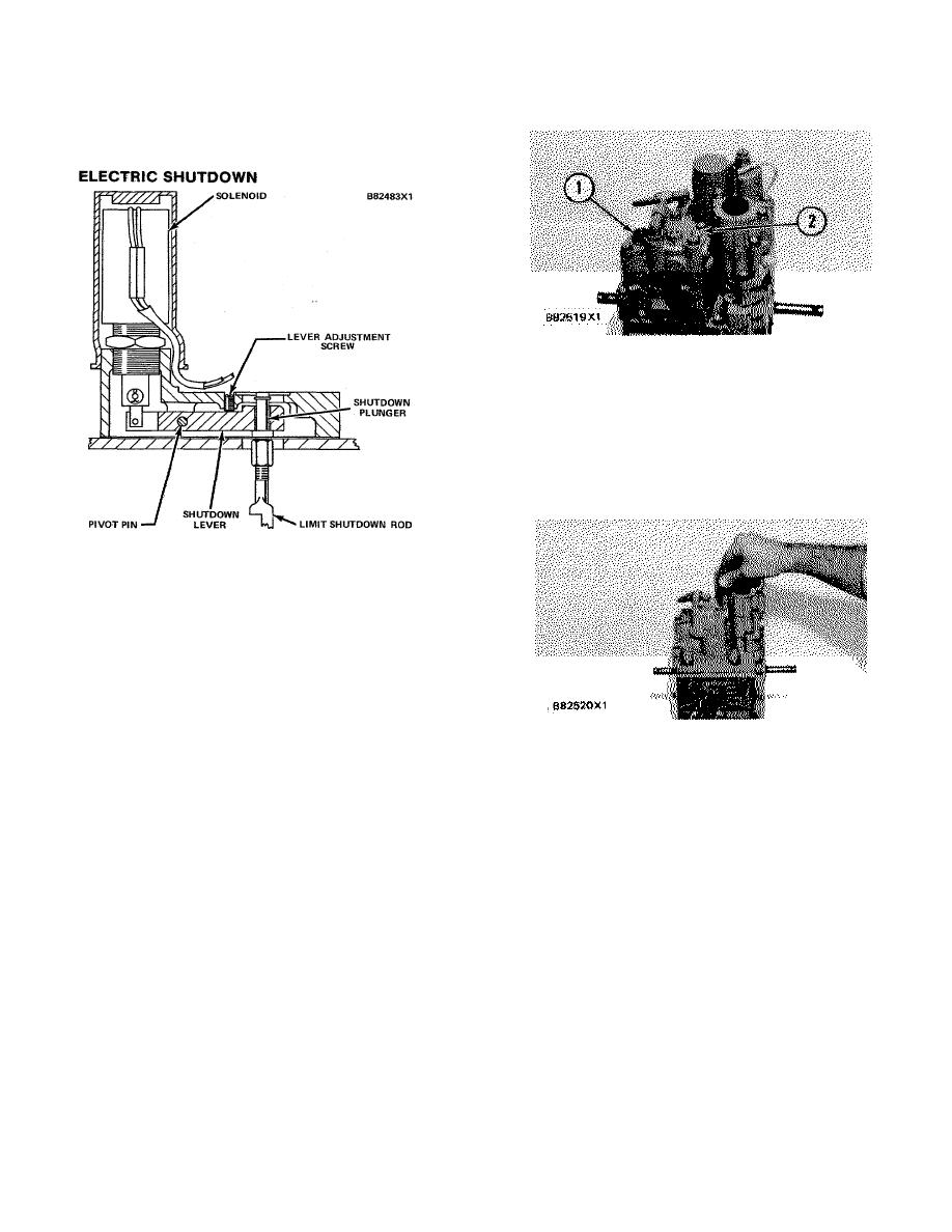
ELECTRIC SHUTDOWN
PNEUMATIC SPEED SETTING CONTROL 1. Bellows.
2. Plug over low idle adjustment screw.
The other is the pneumatic speed level ratio
(bias spring) adjustment, made by removing plug (2) and
turning the adjustment screw with a 1/8 inch hex wrench.
Pneumatic Speed Level Ratio Adjustment
The shutdown lever in the electric shutdown
assembly is adjusted up or down to keep the shutdown/
limit rod in the correct position until the shutoff solenoid
is activated.
1.
Install the gasket and electric shutdown on top of
the governor. Tighten the bolts to 10 Nom (90 lb. in.).
2.
Remove the cover, manual shutdown or
pressure shutdown, if so equipped, from the top of the
electric shutdown assembly.
ADJUSTMENT OF LOW IDLE
3.
Turn the adjustment screw until the shutdown
When the speed level adjusting screw is turned
plunger is even with the top of the gasket for the cover or
the low speed setting of the pneumatic control is
other shutdowns.
changed.
4.
Install the cover, manual shutdown or pressure
With the plug removed, put a 1/8 in. hex wrench
shutdown, if so equipped.
in the hole until it engages with the adjustment screw.
Turn the screw clockwise to decrease the low idle
PNEUMATIC
SPEED
SETTING
CONTROL
setting. Turn the screw counterclockwise to increase the
ADJUSTMENTS
low speed setting.
The pneumatic speed setting control has two
Feedback Spring
adjustments.
One is the speed range bellows
adjustment made by turning the bellows (1) inside the
To use the pneumatic speed setting control with
bellows housing to increase or decrease the speed
different air pressure ranges and engine speed settings
range.
the feedback spring must be changed.
192
|
||
|
||


