
| Tweet |

Custom Search
|
|

|
||
 HYDRAMECHANICAL PROTECTIVE SYSTEM
SPECIFICATIONS
camshaft drive gear is in full contact with the taper on the
TACHOMETER AND SERVICE
camshaft.
METER DRIVE
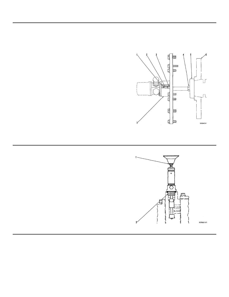
(5)
Tachometer drive adapter.
(6)
Camshaft drive gear.
(1)
Put clean engine oil or glycerin on the O-ring
(7)
Cover.
seal at assembly.
(2)
Bearing.
(3)
Install seal in cover (7) with the lip of the seal
toward bearing (2). Put clean engine oil on the
lip of the seal after it is installed.
(4)
Bolts. Tighten the bolts as follows:
a. Use hand pressure to turn and hold
camshaft drive gear (6) in its normal
direction of rotation. This removes all gear
clearance (backlash) between camshaft
drive gear (6) and the idler gear.
b. Install tachometer drive adapter (5) to hold
the camshaft drive gear to the camshaft.
c. Tighten the bolts in steps to a torque of
10015 Nm (75 = 11 lb. ft.)
d. Hit the face of tachometer drive adapter (5)
and tighten bolts to a torque of 10015
Nm (7511 lb. ft.).
e. Again hit the face of tachometer drive
adapter (5) and again tighten the bolts to a
torque of 100 + 15 Nm (75 + 11 lb. ft.).
NOTE: If necessary, repeat steps above until the bolts
hold torque (cannot be moved) to make sure the
REMOTE SHUTOFF VALVE GROUP
(1)
Locknut.
(2)
Cylinder threads.
Clean threads of cylinder and locknut (1) thoroughly. Put
9S3265
Retaining Compound on threads of cylinder and locknut
at
assembly.
209
|
||
|
||


