
| Tweet |

Custom Search
|
|

|
||
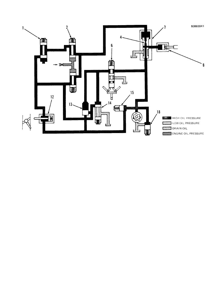 HYDRAMECHANICAL PROTECTIVE SYSTEM
SYSTEMS OPERATION
SCHEMATIC NO. 9 (OVERSPEED FAULT)
1. Selector valve. 2. Low speed oil protection valve. 4. Diverter valve orifice. 6. Speed sensing valve spool. 7.
Diverter valve. 8. Fuel shutoff actuator 12. Air inlet shutoff actuator 13. Air inlet sequence valve. 14. Pilot
operated two-way valve. 15. Fuel shutoff sequence valve. 18. Oil pressure relief valve.
supply to the engine. Fuel shutoff circuit oil also can not
OVERSPEED CIRCUIT (OVERSPEED FAULT)
go to drain. The difference in oil pressure across diverter
valve orifice (4) will now go to zero. The valve spool of
Make Reference to Schematic No. 9.
diverter valve (7) will move down by spring force, which
will cause alignment of the ports to fuel shutoff actuator
When the engine speed is 18% above full load
(8). Now, oil pressure in the fuel shutoff circuit will
speed, speed sensing valve spool (6) will be moved up
activate fuel shutoff actuator (8), which will cause the
by the flyweights. This will send oil to pilot operated two-
governor to move the fuel control linkage to the
way valve (14) and to the spring side of air inlet
"SHUTOFF" position.
sequence valve (13). The oil pressure will close both
valves and oil in the air inlet shutoff system can not go to
NOTE: Because the air inlet shutoff is the most positive
drain. The oil pressure in the system will i crease until oil
way to shutdown an engine, air inlet shutoff actuator (12)
pressure relief valve (18) opens at 1720kPa (250psi).
is activated by the protective system before fuel shutoff
The increase pressure will move air inlet shutoff actuator
actuator (8) is activated.
(12), which will release the air inlet shutoff valve. This
stops the combustion air
224
|
||
|
||


