
| Tweet |

Custom Search
|
|

|
||
 3500 ENGINES
DISASSEMBLY AND ASSEMBLY
MANUAL SHUTOFF
INSTALL MANUAL SHUTOFF
7418-12
Tools Needed
A
B
1P510
Driver Group
1
1P1856
Pliers
1
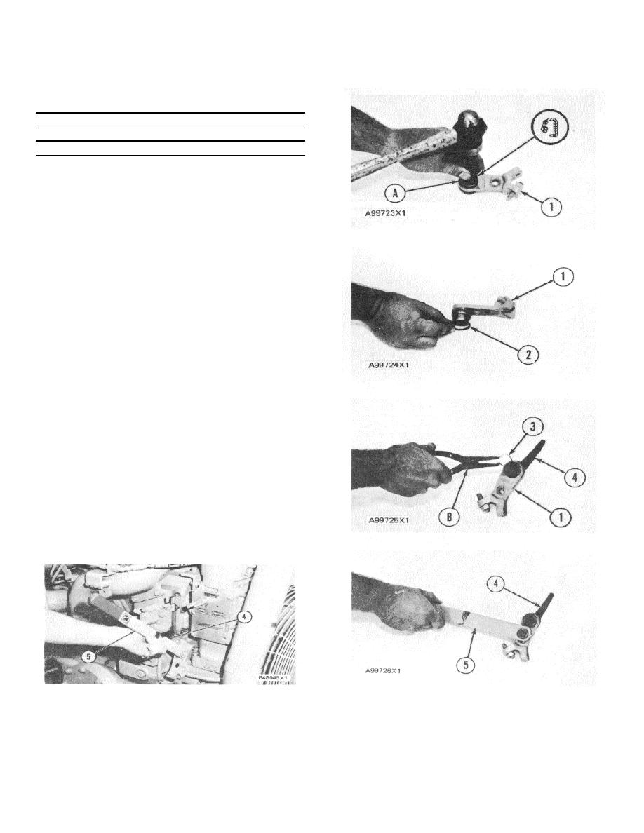
1.
Use tool group (A) and install the seal in adapter
(1) with the lip of the seal toward the inside as
shown. Put clean engine oil on the lip of the
seal.
2.
Install O-ring seal (2) on adapter (1) and put
clean engine oil on it.
3.
Put lever (4) in adapter (1) and use tool (B) to
install ring (3) to hold the unit together.
4
Put lever (5) in position and install the washer
and bolt to hold it to lever (4).
5.
Install the levers and adapter in the front drive
housing. Make sure lever (4) is under and in
contact with the governor stop lever. Install the
bolt and washer to hold the unit in position.
6.
To make an adjustment of the shutoff levers,
loosen the locknut and screw on the adapter.
Pull lever (5) until the governor linkage makes
contact with its stop and hold lever (5) in this
position. Turn the adjustment screw until it
makes contact with lever (5) and then turn it one
more complete turn. Tighten the locknut.
258
|
||
|
||


