
| Tweet |

Custom Search
|
|

|
||
 3500 ENGINES
DISASSEMBLY AND ASSEMBLY
GOVERNOR
INSTALL GOVERNOR 1264-12
Tools Needed
A
1P510
Driver Group
1
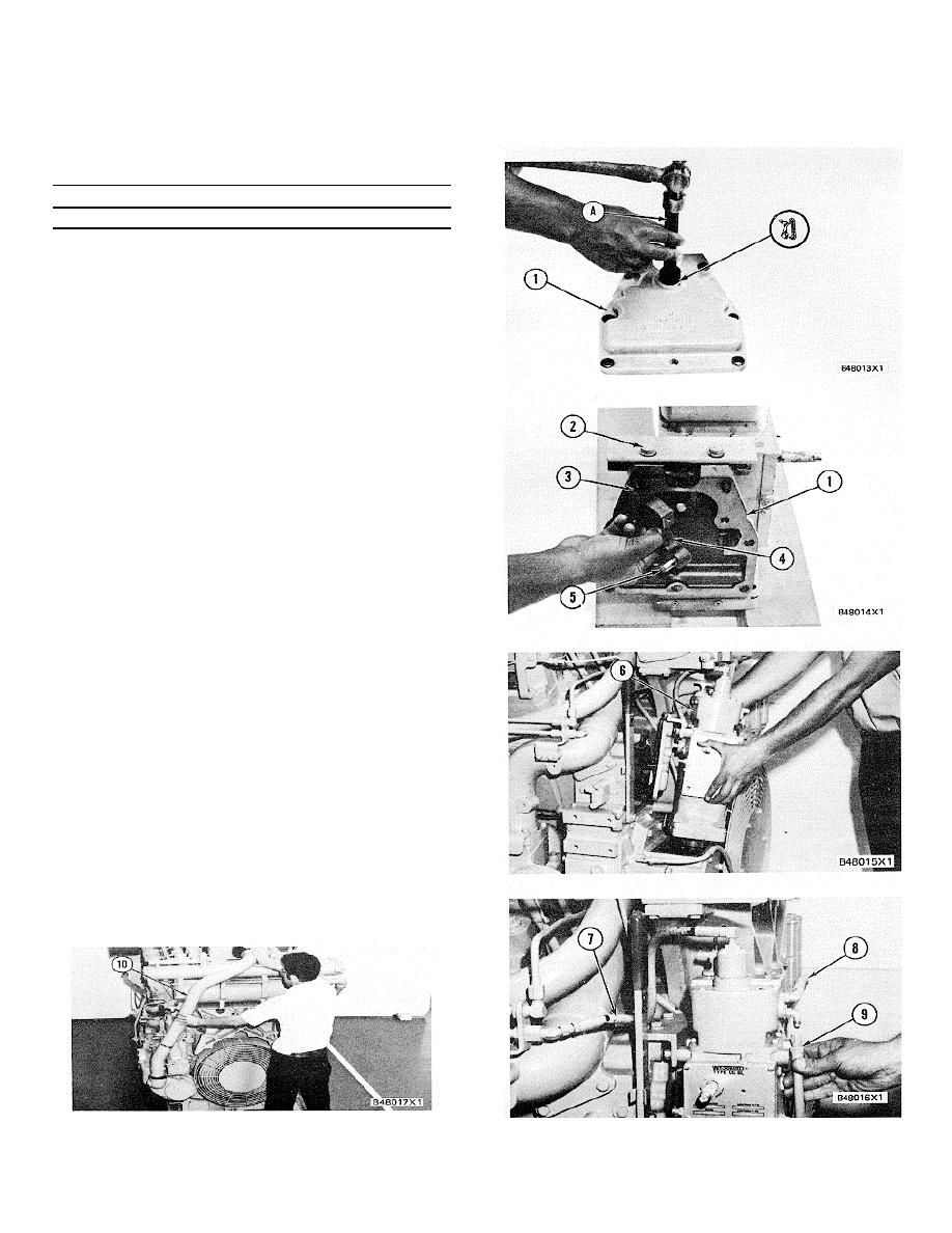
1.
Install the washer in cover (1) and use tool group
(A) to install the seal in cover (1). Make sure the
lip of the seal is toward the engine as shown and
put clean engine oil on the seal.
2.
Make sure two bolts (3) are in position and put
cover (1) in position on the governor.
Install.48013X1 bolts (2) to hold the cover in
position.
3.
If pin (5) was removed, use a press to install the
new pin until it is 18 1 mm (.71 .04 in.)
above the surface of the lever assembly as
shown. Put lever assembly (4) in position on the
governor output shaft and install the bolt to hold
it.
4.
Put the gaskets for the governor and the
fastener group in position on the engine. Fasten
a hoist or use two men to put governor (6) and
the fastener group as a unit in position on the
engine. Make sure the pin on lever assembly (4)
engages in the groove (slot) of the lever for the
fuel control. Make sure the splines on the
governor input shaft are engaged correctly in the
governor drive and install the bolts to hold the
governor and fastener group in position.
5.
Install hose assembly (7) on the governor and
connect it to the engine.
Connect hose
assemblies (8) and (9) to the governor.
6.
Put clean engine oil on the O-ring seals and'
install tube (10) on the engine. Install the bolts
and retainers to hold the tube in place.
7.
Fill the cooling system with coolant to the correct
level.
327
|
||
|
||


