
| Tweet |

Custom Search
|
|

|
||
 3500 ENGINES
DISASSEMBLY AND ASSEMBLY
ROCKER SHAFTS AND PUSH RODS
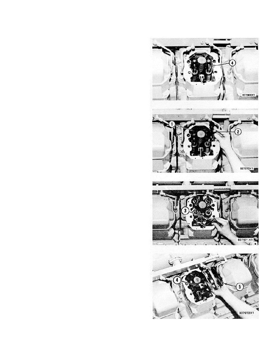
3.
Remove bridge assemblies (4) from the dowels.
INSTALL ROCKER SHAFTS AND
PUSH RODS
1102 & 1208-12
1.
Loosen the adjustment nuts and screws (1) on
valve bridges (2)
2.
Put clean engine oil on the bridge dowels, the
inside diameter of valve bridges (2) and on the
top pad of the valve bridge. Install valve bridges
(2) on the bridge dowels as shown.'
3.
While bridges (2) are pushed straight down with
a force of 25 + 20 N (5.6 + 4.5 lb.) on the top
contact surface, turn adjustment screw (1) : until
it makes contact with the valve stem. Turn :
screw (1) another 200 to 300.
This will
straighten the dowel in the guide and make
compensation for clearance (slack) in the
threads.
4.
Hold adjustment screw (1) in position and,
tighten the nut around screw (I) to a torque of.
30 _ 4 Nm (22 3 lb. ft.).B3797
5.
Put push rods (3) in position in the valve lifters
and valve cover base.
NOTICE
Make sure the crankshaft and
camshafts are in time with each
other and that adjustment screws (5)
are turned all the way out before the
rocker shaft bolts are tightened or
damaged to, the valves or pistons
can be the result.
See INSTALL
CAMSHAFTS for the procedure to
time the engine.
6.
Put the rocker arms and shaft (4) in position on
the valve cover. Make sure the rocker shafts
and push rods are in alignment and install the
bolts to hold shaft (4).
7.
Make an adjustment of the valves to have a
clearance of 0.40 mm (.016 in.) for intake and
0.76 mm (.030 in.) for exhaust. See VALVE
CLEARANCE SETTING in TESTING" AND
ADJUSTING section for the complete procedure.
a)
install valve covers.
366
|
||
|
||


