
| Tweet |

Custom Search
|
|

|
||
 3500 ENGINES
DISASSEMBLY AND ASSEMBLY
ROCKER SHAFT ASSEMBLIES
ASSEMBLE ROCKER SHAFT
ASSEMBLIES
1102-16-
Tools Needed
A
1P510 Driver Group
1
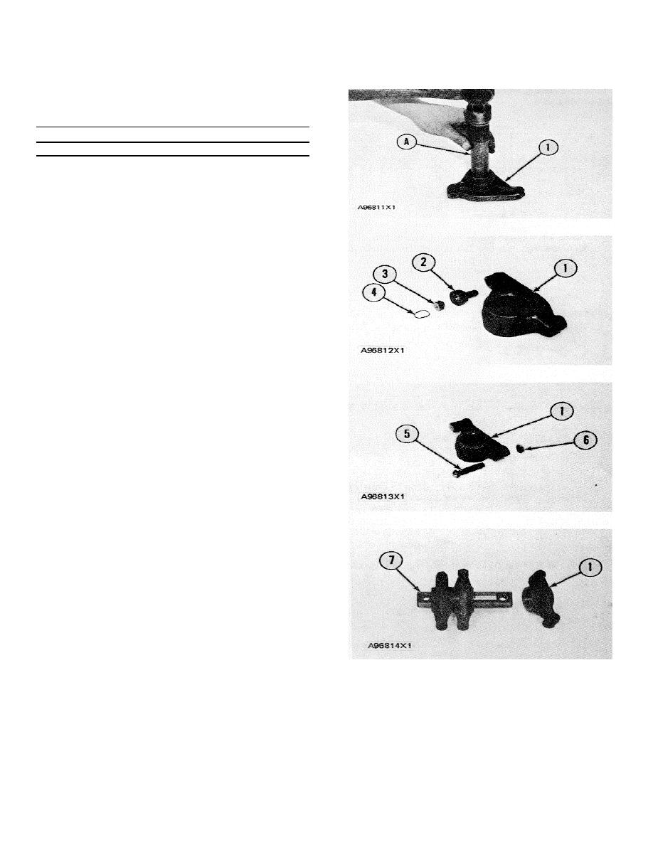
1.
Make an alignment of the oil hole (slot) in the
bearing with the oil passage in rocker arm (1).
Use tool group (A) to install the bearing in rocker
arm (1) with the joint in the bearing toward the
top of the rocker arm. The bore in the bearing
must be 37.140 0.015 mm (1.4622 .0006 in.)
after assembly.
2.
Make an alignment of the scribe mark on socket
(2) with the mark on rocker arm (1) and install
the socket in the rocker arm.
3.
Put button (3) in socket (2) and install ring (4) to
hold the unit together.
4.
Install adjustment screw (5) and nut (6) on
rocker arm (1).
5.
Do Steps I through 4 for the other two rocker
arms.
6.
If the dowel was removed from shaft assembly
(7), install the new dowel in the shaft until it is 7.7
0.5 mm (.303 .020 in.) above the-surface of
the shaft.
7.
Put clean engine oil on the rocker arm bearings
and shaft assembly (7). Install rocker arms (1)
on shaft assembly (7).
end by:
a) install rocker shafts and push rods
368
|
||
|
||


