
| Tweet |

Custom Search
|
|

|
||
 3500 ENGINES
DISASSEMBLY AND ASSEMBLY
CYLINDER HEADS
9.
Make sure the three O-ring seals are installed on
injector (6) and put clean engine oil on them and
in the bore for the injector.
NOTICE
Do not tap or hit on the injector follower to install the
injector. Damage and failure to the injector can be
the result.
10.
Put injector (6) in position. Install the clamp,
washer and bolt. Tighten the bolt to push
injector (6) all the way in its bore. Tighten the
bolt to a torque of 65 + 7 Nm (48 + 5 lb. ft.).
11.
Check to make sure the fuel injection rack
moves freely by hand in the injector after the
injector is installed.
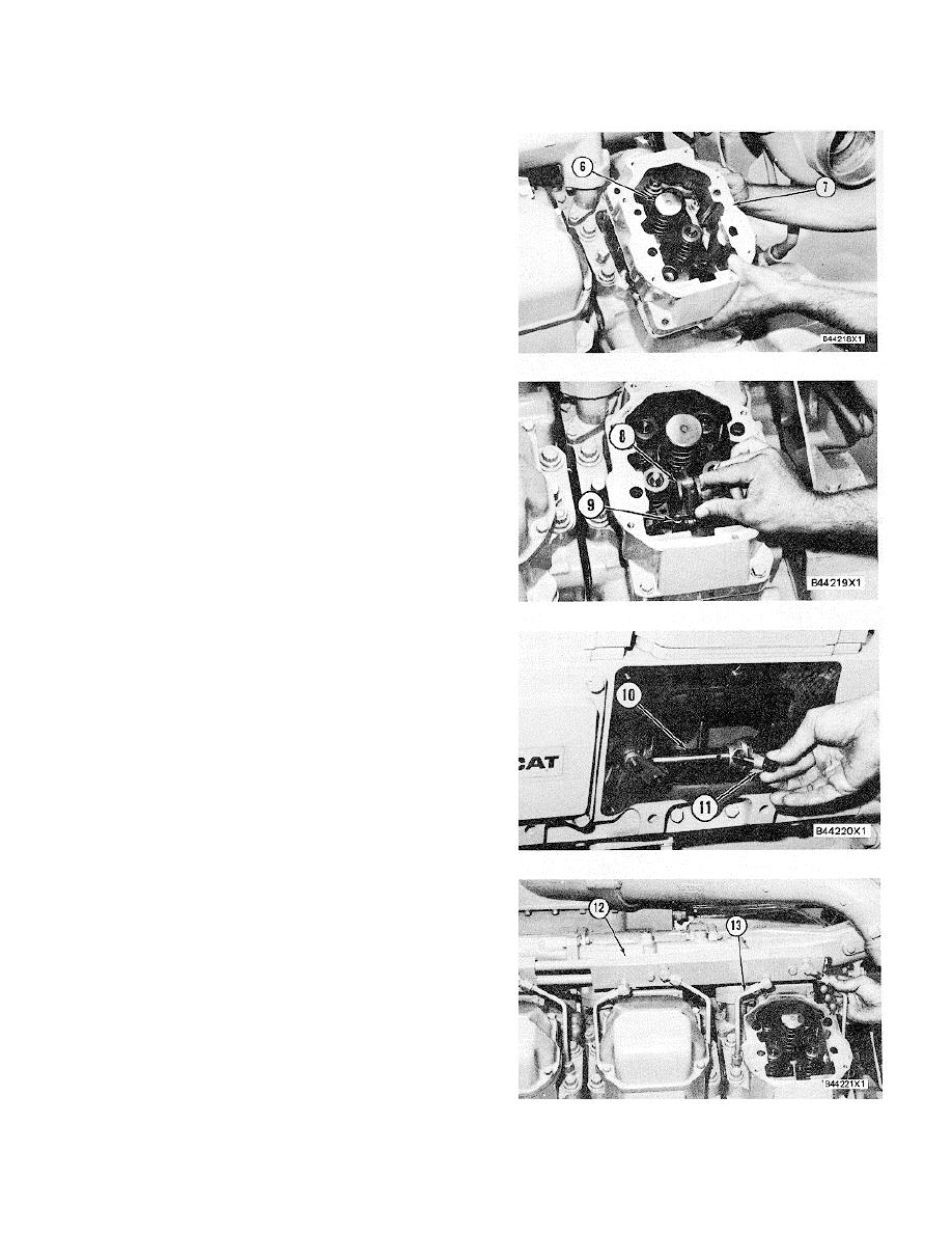
12.
Make sure the O-ring seals are installed around
the three dowels in the bottom of valve cover
base (7). Put the gasket and base (7) in position
and install the bolts to hold them to the cylinder
head.
13.
Put fuel control rod assembly (9) and lever
assembly (8) in position in the cylinder head. If
necessary, use tool (B) to turn the engine fly
44219Xl
wheel until the camshaft moves
enough to permit the lever of rod assembly (9) to
move into position.
14.
Make sure lever assembly (8) is engaged
correctly with the fuel injection rack and install
the two bolts and washers to hold it in place.
15.
See TESTING AND ADJUSTING section for
the correct adjustment of the fuel injection
control group.
16.
Make sure the lever for the fuel control and
assembly is in position on control shaft (10) and
install the bolt and cap (11).
17.
Install the access cover and seal over the
camshaft and control shaft (10).
18.
Make sure the 0-ring seals for the fuel manifold
and lines are installed and have clean engine oil
on the seals. Install fuel manifold (12) and fuel
lines (13) on the engine.
19.
Turn the fuel supply to the engine.
20.
Fill the cooling system with coolant to the correct
level.
end by:
a) install rocker shafts and push rods
380
|
||
|
||


