
| Tweet |

Custom Search
|
|

|
||
 3500 ENGINES
DISASSEMBLY AND ASSEMBLY
CAMSHAFT BEARINGS, CRANKSHAFT
b)
Follow Steps 2, 3 and 4 to install the
tooling and pull the bearing into the
center of its bore.
c) Check the bore in bearing (1) after it is
installed. The bore must be 86.00 +
0.06 mm (3.386 + .002 in.).
end by:
a) install camshafts
REMOVE CRANKSHAFT
1202-11
start by:
a) remove rocker shafts and push rods
b) remove front drive housing
c) remove front balancer group (3508)
d) remove rear gear group (Step 1 only)
e) remove piston cooling jets
NOTICE
The rocker shafts and push rods do not have to be
removed to remove the crankshaft but bent push
rods can be the result if they are not removed.
1. Put the engine in the position as shown.
The weight of the 3512 Engine is
approximately 5443 kg (12, 000 lb.). The
weight of the 3508 Engine is approximately
4445 kg (9800 lb.).
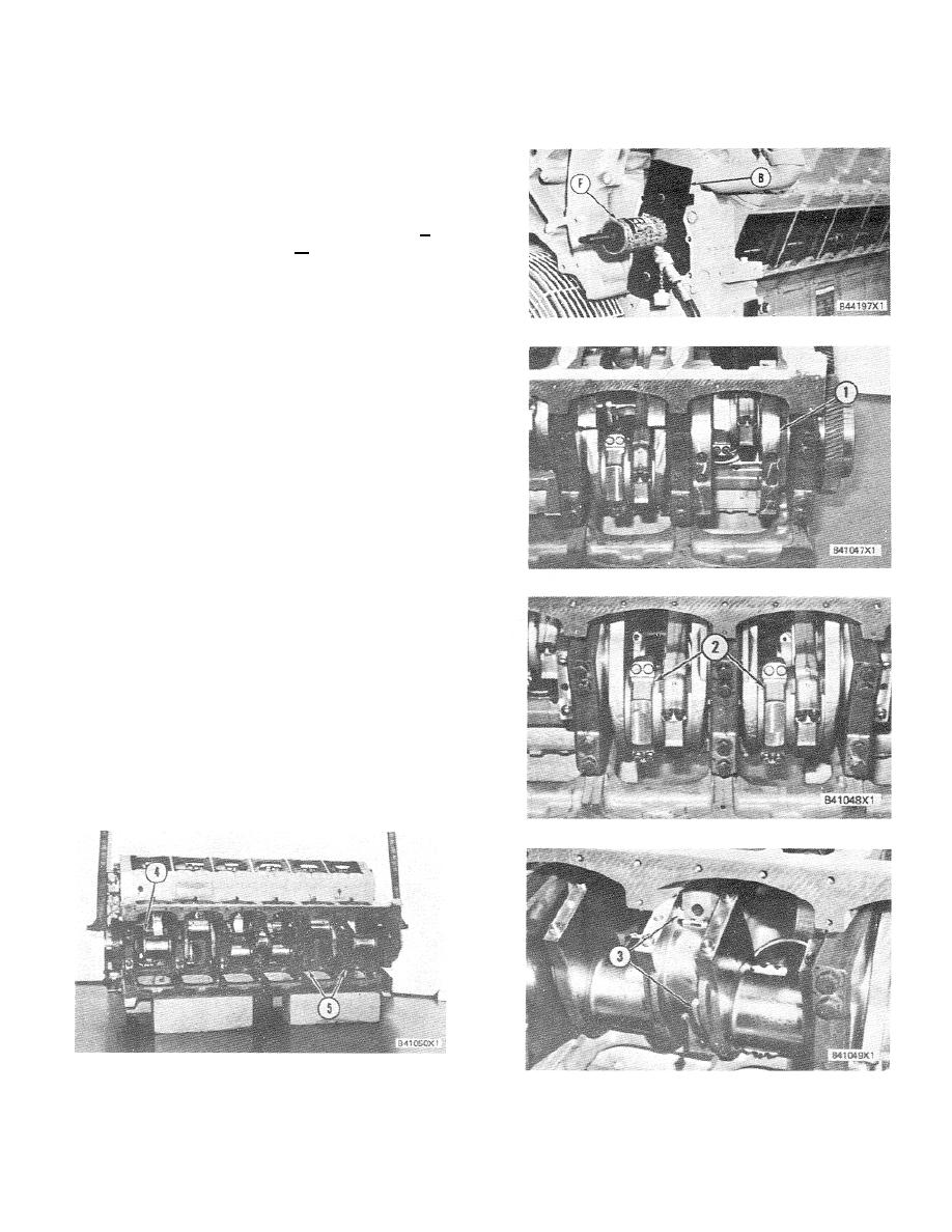
2. Remove counterweights (1) from the
crankshaft.
3. Remove bearing caps (2) from the
connecting rod and push the connecting
rods away from the crankshaft. Use wire to
hold the upper half of the connecting rods
away from the crankshaft.
4. Remove the center main bearing cap and
remove two thrust plates (3) from each side
of the main bearing.
5. Use two of the bolts that hold the flywheel
to the crankshaft and install a bolt in each
end of the crankshaft. Fasten a hoist to the
crankshaft as shown.
407
|
||
|
||


