
| Tweet |

Custom Search
|
|

|
||
 ELECTRIC PROTECTIVE SYSTEM
TROUBLESHOOTING
PROCEDURE E
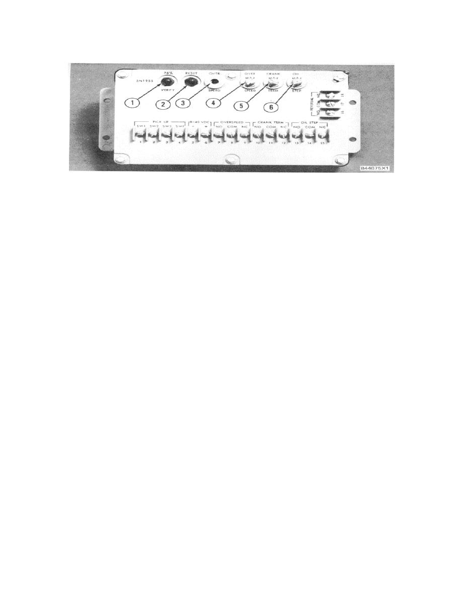
5N1955 ELECTRONIC SPEED SWITCH
1. Verily button. 2. Reset button. 3. "LED" overspeed light. 4. Seal screw plug (overspeed). 5. Seal screw plug
(crank terminate). 6. Seal screw plug (oil step).
Assembly according to Procedure F.
REVERSAL DETECTION
NOTE: Different wiring connections must be used for
1.
Stop the engine and reverse the wires from
engines with different rotation. For a specific engine
PICKUP terminals SW1 (ESS-1) and SW2
rotation, use the correct connections that follow:
(ESS-2) [this will simulate an engine reversal
when the engine is cranked at least two full
revolutions]. Connect the 6V3030 Multimeter or
*STANDARD ROTATION (Counterclockwise)
a voltmeter between terminals ESS-16 and ESS-
Connect -
5. Crank the engine at least two full revolutions
White wire from sensor assembly to
and check for positive (+) voltage at ESS16. If
PICKUP terminal SW1 (ESS-1).
voltage is indicated, the reversal detection is
functioning properly.
Dark green wire from sensor assembly to
PICKUP terminal SW2 (ESS-2).
2.
To reset the reversal function, connect again
SW1 wire (white) back on terminal ESS-1 and
*REVERSE ROTATION (Clockwise)
SW2 wire (dark green) back on terminal ESS-2.
Connect -
Crank the engine at least two full revolutions and
Dark green wire from sensor assembly to
check for positive (+) voltage at ESS-16. No
PICKUP terminal SW1 (ESS-1)
voltage should be indicated.
White wire from sensor assembly to
3.
If no voltage is indicated, then reversal function
PICKUP terminal SW2 (ESS-2).
has reset correctly.
*Rotation as viewed from flywheel end of engine.
4.
If voltage is still indicated, crank the engine again
and check PICKUP wires for proper connection.
If voltage is still indicated, check 7N7412 Sensor
500
|
||
|
||


