
| Tweet |

Custom Search
|
|

|
||
 ELECTRIC PROTECTIVE SYSTEM
TROUBLESHOOTING
C
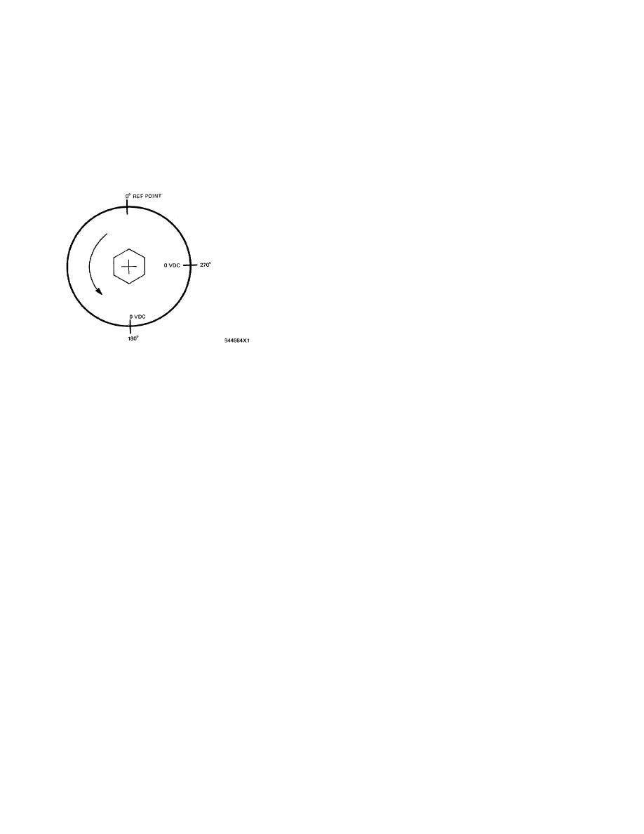
With the negative (-) voltmeter lead still
connected to ESS-5, connect the positive ( + )
voltmeter lead to SW3 (ESS-3). Again, slowly
turn the sensor shaft counterclockwise. A 4 to 6
VDC reading should be seen for all but two small
areas of shaft rotation; one at the 1800 interval
and one at the 2700 interval (both measured
from the SWI 0 reference point). Zero volts will
be indicated at both of these areas.
SW3 CHECK
2.
If all four zero volt levels are recorded in the
proper sequence and at the proper degree of
rotational position (900 apart from each other),
then the 7N7412 Sensor Assembly operates
properly.
3.
Before installing 7N7412 Sensor Assembly (2)
back on the engine, start the engine and check
to be sure that the drive shaft in tachometer
drive housing (1) is turning properly.
4.
If tachometer drive shaft is in rotation, stop
engine and install sensor assembly.
NOTE: The tachometer drive housing has two output
drives (one marked A and the other marked B).
Be sure that sensor assembly is always
connected to output drive marked A.
502
|
||
|
||


