
| Tweet |

Custom Search
|
|

|
||
 ELECTRIC PROTECTIVE SYSTEM
TROUBLESHOOTING
PROCEDURE E
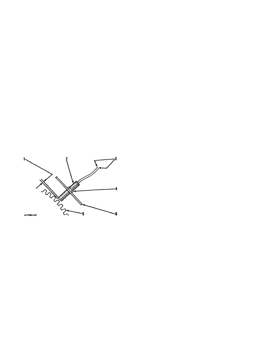
3.
Remove magnetic pickup (2) from the engine
MAGNETIC PICKUP VERIFY
flywheel housing (earlier location, front drive
housing) and turn the flywheel until a gear tooth
1.
Connect a 6V7070 Multimeter (or a voltmeter of
(5) is directly in the center of the threaded
same accuracy) to electronic speed switch
opening for the magnetic pickup. Install the
common terminal (ESS-3) and signal terminal
magnetic pickup again in the threads of housing
(ESS4). Set the meter voltage scale to a scale
(6).
greater than 1.5 VAC. Start the engine and run
at idle rpm or 600 rpm (whichever is greater).
By hand, turn in a clockwise direction until the end
of the magnetic pickup just makes contact with the gear
If the measured voltage is 1.5 VAC or more, the
tooth (5). Now turn the magnetic pickup back out 1/2
operation of the magnetic pickup is correct. If measured
turn (180 in the counterclockwise direction) to get the
voltage is less than 1.5 VAC, go to Step 2.
correct air gap [clearance dimension (1)]. Now tighten
locknut (4) to a torque of 68 13 Nm (50 + 10 lb. ft.).
2.
Disconnect the wiring from the magnetic pick- up
and connect the voltmeter to magnetic pick- up
NOTE: Do not let the magnetic pickup turn while
connector terminals I and 2. Set the volt- meter
locknut is tightened.
voltage scale to a scale greater than 1.5 VAC.
Start the engine and run at idle rpm or 600 rpm
Do Step 2 again. If voltage is still less than 1.5
(whichever is greater).
VAC, replace the magnetic pickup.
If the measured voltage is 1.5 VAC or more,
repair or replace the wiring between the magnetic pickup
and the electronic speed switch. If the measured voltage
is less than 1.5 VAC, go to Step 3.
MAGNETIC PICKUP
1. Clearance dimension. 2. Magnetic pickup. 3.
Wires. 4. Locknut. 5. Gear tooth. 6. Housing.
552
|
||
|
||


