TM 5-2815-241-34&P
VALVE AND INJECTOR ADJUSTMENTS - CONTINUED
ACTION
LOCATION
ITEM
REMARKS
DIAL INDICATOR METHOD - CONTINUED
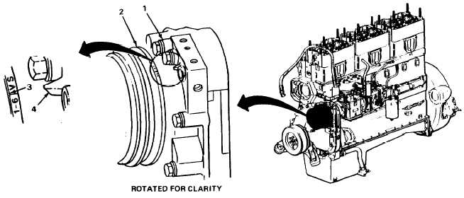
5. Gearcase cover (1)
Accessory drive
Using crankshaft barring tool, rotate
pulley (2) timing
crankshaft in direction of engine rotation
mark (3), and
until timing mark A or 1-6 VS is alined with
pointer (4)
pointer.
NOTE
Both intake and exhaust rocker arm for cylinder number five must be loose (valves
closed). Injector plunger for cylinder number three must be at top of travel before
beginning adjustment.
6. Rocker arm
housing (5)
Number five cylinder
(6), intake rocker arm
(7) and exhaust
rocker arm (8)
Both rocker arms must be loose.
If rocker arms are not loose, repeat
step 5.
7. Rocker arm
housing (9)
Number three cylin-
der (10) and injector
plunger (11)
Injector plunger must be at top of travel.
If not at top of travel, repeat step 5.
T A 2 4 2 4 0 1
2-108
|
|