TM 5-2815-241-34&P
VALVE AND INJECTOR ADJUSTMENTS - CONTINUED
ACTION
LOCATION
ITEM
REMARKS
DIAL INDICATOR METHOD - CONTINUED
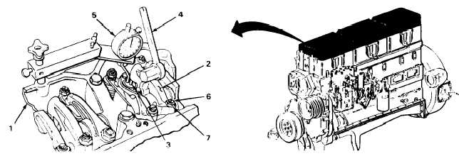
10. Rocker arm
housing (1)
Injector rocker arm
(2), injector plunger
(3) and ST-1193
rocker arm
actuator (4)
11.
12.
13.
14.
ST-1170 dial
indicator (5)
Adjusting screw (6)
and locknut (7)
Rocker arm (2) and
injector plunger (3)
Adjusting screw (6)
and locknut (7)
a.
Using ST-1193 rocker arm actuator,
press injector rocker arm down toward
fuel injector until fuel injector reaches
bottom.
b.
Release rocker arm and press down
again.
Set ST-1170 dial indicator to zero.
Using 3/8-inch drive ST-669 adapter set
and 1/4-inch drive 7/16-inch socket, screw
in until ST-1170 dial indicator reads 0.170
inch (4.3 mm).
Bottom plunger and release rocker arm to
allow injector plunger to rise.
ST-1170 dial indicator must show
travel of 0.170 inch (4.32 mm).
Using 3/8-inch drive ST-669 adapter set
and 1/4-inch drive 7/16-inch socket,
and 0 to 150 ft lb (0 to 210 N•m) torque
wrench, torque locknut to 25 to 35 ft lb
(35 to 49 N°m).
Check adjustment by performing steps
10 thru 14 again.
T A 2 4 2 4 0 3
2-110
|
|