TM 5-2815-241-34&P
ANEROID CONTROL VALVE INSTALLATION
INITIAL SETUP
Tools
Materials/Parts
Extension, 6-inch, 1/2-inch drive
Socket, 9/16-inch,1/2-inch drive
Wrench, open-end, 9/16-inch
Wrench, open-end, 5/8-inch
Wrench, open-end, 7/8-inch
Wrench, torque, 0 to 50 ft lb (0
to 70 N•m), 1/2-inch drive
Lockwasher (two required)
Equipment Condition
Intake manifold installed (page 2-119).
ACTION
LOCATION
ITEM
REMARKS
2.
Fuel line nuts (7)
3.
Fuel line nuts (8)
4.
Vacuum line nut (9)
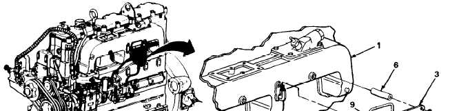
1. Intake manifold (1)
Aneroid control
valve (2), bracket
(3), two screws (4)
two new lockwashers
(5) and two
spacers (6)
a.
Position aneroid control valve on
intake manifold.
b.
Using 1/2-inch drive 9/16-inch socket,
6-inch extension, and 0 to 50 ft lb torque
wrench (0 to 70 N•m), screw in and
tighten to 20 to 25 ft lb (28 to 35 N•m)
torque.
Using 5/8-inch and 7/8-inch open-end
wrenches, put on and tighten.
Using 5/8-inch and 9/16-inch open-end
wrenches, put on and tighten.
Using 9/6-inch open-end wrench, put on
and tighten.
TASK ENDS HERE
TA 242421
2-132
|
|