TM 5-2815-241-34&P
CYLINDER BLOCK - CONTINUED
I
ACTION
LOCATION
ITEM
REMARKS
REPAIR - CONTINUED
WARNING
Safety goggles must be worn to prevent eye injury caused by flying steel chips.
NOTE
Step 28 is for main bearing capscrew threads tagged for repairs and steps 29 thru 35 are
for cylinder block tagged for sleeve lower bore repairs.
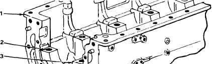
28. Cylinder block (1)
Main bearing
capscrew hole (2)
a.
Using 1/2-inch portable electric drill
and 1 1/32-inch bit, drill hole 2.675 to
2.705 inches (68.16 to 68.74 mm)
deep from main bearing cap pad (3).
b.
Using ST-1230 screw thread insert kit,
tap hole of 2.425 to 2.455 inches (61.60
to 62.36 mm) deep.
c.
Using inserting tool from kit, install
screw thread insert 0.860 to 0.890 inch
(21.84 to 22.61 mm) deep below main
bearing cap pad (3).
29. Cylinder block (1)
ST-1081 boring
tool (4)
Install assembled ST-1081 boring tool,
allowing bore adapter (5) to engage count-
erbore, and holes in adapter plate (6) to
match holes in cylinder block.
30.
Adapter plate (6)
a.
Fasten in place with capscrews (7).
b.
Using 1/2-inch drive, 1 1/16-inch socket,
and 0 to 150 ft lb (0 to 210 N•m)
torque wrench, screw in and torque cap-
screw 50 to 75 ft lb (6.9 to 10.4 kgm).
TA 242436
2-156
Change 1
|
|