TM 5-2815-241-34&P
CYLINDER HEAD - CONTINUED
ACTION
LOCATION
ITEM
REMARKS
INSPECTION - CONTINUED
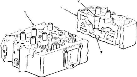
11. Cylinder head (1)
Injector sleeve (2)
Visually inspect cup seating area (3)
for scratches.
If cup seating area is scratched, tag
for replacement. See steps 35
thru 48.
12. Cup seating area (3)
13. Injector sleeve (2)
Injector cup (4)
Injector
assembly (5)
Lightly coat injector cup with prussian
blue.
a. Using 1/2-inch drive 1/2-inch socket,
3-inch extension, and ratchet handle,
install injector assembly. Secure
with clamp (6) and capscrews (7).
Using 1/2-inch drive, 1/2-inch
socket, and 0 to 175 ft lb (0 to
245 N•m) torque wrench, tighten
capscrews (7) alternately In 4 ft lb
(5.4 N•m) Increments to 10 to 12 ft lb
(13.5 to 16.2 N•m).
b.
Using 1/2-inch drive 1/2-inch socket,
3-inch extension, and ratchet handle,
remove capscrews (7) clamp (6), and
injector assembly.
T A 2 4 2 4 5 5
2-182
Change 1
|
|