TM 5-2815-241-34&P
CYLINDER HEAD - CONTINUED
ACTION
LOCATION
ITEM
REMARKS
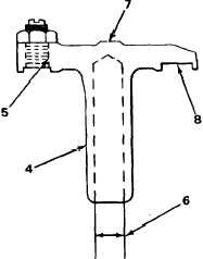
b. Inspect adjusting screw threads (5)
and crosshead threads for wear or
distortion.
If adjusting screw threads (5) or
crosshead threads are damaged, dis-
card valve crosshead.
c.
Set dial bore gage at 0.4402 inch
(11.181 mm). Attempt to Insert gage
into bore (6).
If bore gage goes Into bore (6), dis-
card valve crosshead (4).
d. Check for out of round bore by gaging
at several points 90 degrees apart.
If bore Is out of round, discard
valve crosshead (4).
e. inspect for excessive wear on rocker
arm contact area (7) and on valve stem
contact area (8).
If excessive wear Is found on either
rocker arm contact area (7) or valve
stem contact area (8), discard valve
crosshead (4).
T A 2 4 2 4 6 0
2-187
|
|