TM 5-3895-360-13
6-3. ENGINE CRANKSHAFT, PISTON, AND CONNECTING ROD REPLACEMENT (Con’t).
h.
i.
j.
k.
l.
m.
n.
Inspect connecting rod for cracks, breaks, and dam-
aged threads. Restore damaged threads using die
and tap threading set.
NOTE
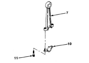
Refer to Figure 6-14, Measuring Connecting
o.
Rod Bores, for steps i through n.
Using inside caliper micrometer, measure piston pin
bore diameter of connecting rod (7). Measurement
must be 0.6870-0.6875 in. (17,4498-17.4625 mm).
Replace connecting rod if measurement is not within
specification.
Place connecting-rod (7) in vise with caps,
install connecting rod cap (10) on connecting rod (7)
with two screws (11 ).
Using inside caliper micrometer, measure bore di-
ameter of connecting rod (7) and connecting rod cap
(10). Diameter must be 0.9399-0.9403 in.
(23.8735-23.8836 mm).
Remove two screws (11) and connecting rod cap
(10) from connecting rod (7).
Remove connecting rod (7) from vise.
NOTE
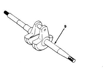
Refer to Figure 6-15, Measuring Crankshaft,
for step o.
Using outside caliper micrometer, measure connect-
ing rod surface of crankshaft (9). Measurement must
be 0.7493-0.7496 in, (19.0322-19.0398 mm). Re-
place crankshaft if measurement is not within speci-
fication.
Figure 6-15. Measuring Crankshaft.
p. Using inside caliper micrometer, measure cylinder
bore diameter at three points:
(1) Measure ¼ in. (6.35 mm) down from top of cylin-
der.
(2) Measure ¼ in. (6.35 cm) up from exhaust port.
(3) Measure 3/16 in. (4.76 mm) down from lower
edge of intake port
Figure 6-14. Measuring Connecting Rod Boxes.
6-12
|
|