*
C2
PAR 74, STEPS 1 3 - 16
D I S A S S E M B LY
C H A P 5, S E C ii
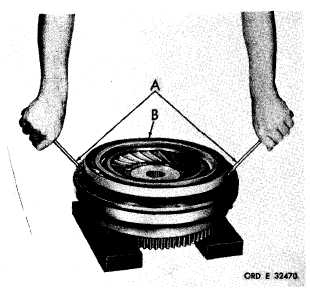
Figure 51 (Step 13)
U s i n g t w o s c r e w d r i v e r s ( A ) , r e m o v e t o r q ue
converter turbine assembly (B).
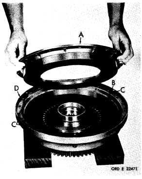
Figure 53 (Step 15)
Remove lockup clutch piston (A) by bumping
converter cover assembly (B) lightly on wooden
b l o c k s ( C ) . R e m o v e h o o k - t y p e s e a l r i n g ( D)
from hub of the cover assembly.
Do not re-
m o v e s e a l r i n g ( E ) a n d e x p a n d e r f r o m t he
l o c k u p c l u t c h p i s t o n u n 1 e s s r e p l a c e m e n t is
n e c e s s a r y .
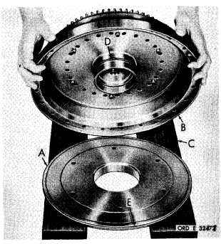
Figure 52 (Step 14)
Remove lockup clutch reaction plate (A), lock-
up clutch plate (B) and three jackscrews (C)
f r o m c o n v e r t e r c o v e r a s s e m b l y ( D ).
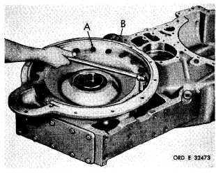
Figure 54 (Step 16)
U s i n g a 5 / 8 - i n c h w r e n c h , r e m o v e 2 0 s e l f-
l o c k i n g b o l t s ( A ) a n d f l a t w a s h e r s r e t a i n i n g
flange adapter (B).
8
1
|
|