P A R 7 5 S T E P S 1 9 - 2 2
D I S A S S E M B LY
C H A P 5, SEC I I
Figure 85 (Step 21)
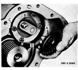
Remove output oil pump driven gear (A) and
k e y ( B ) . U s i n g a 9 / 1 6 - i n c h w r e n c h , r e m o ve
four self-locking bolts (C) retaining oil pump
( D ) . R e m o v e o i l p u m p ( D ).
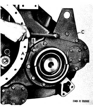
Figure 83 (Step 19)
Using a 5/8-inch wrench, remove 13 bolts (A),
lock washers (B) and lifting bracket (C).
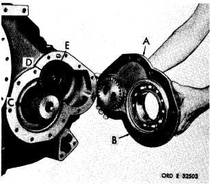
Figure 84 (Step 20)
Remove left-output support assembly (A), gas-
ket (B) and output oil pump drive gear (C).
Remove snap ring (D) retaining oil pump driven
gear (E).
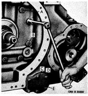
Figure 86 (Step 22)
U s i n g a 5 / 8 - i n c h w r e n c h , r e m o v e f i v e c o n-
v e r t e r - t o - m a i n t r a n s m i s s i o n h o u s i n g a s s e m-
b l y b o l t s ( A ) a n d f l a t w a s h e r s ( B ) . U s i n g a
9 / 1 6 - i n c h w r e n c h , r e m o v e s i x b o l t s ( C ) a nd
lock washers (D) retaining oil screen cover (E).
8
9
|
|