C H A P 5, SEC I I
D I S A S S E M B L Y
P A R 75, S T E P S 3 9 - 4 2
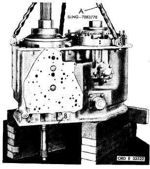
Figure 103 (Step 39)
U s i n g s l i n g ( A ) , p o s i t i o n t r a n s m i s s i o n m a in
h o u s i n g o n d i s a s s e m b l y t a b l e , b l o c k i n g a s-
sembly so turbine shaft (B) clears the table.
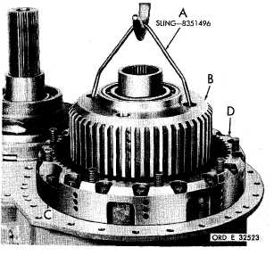
Figure 104 (Step 40)
U s i n g h o i s t a n d s l i n g ( A ) , r e m o v e t h e l e f t-
brake hub and steer planetary assembly (B).
Using a 5/8-inch wrench, remove 18 bolts (C)
from left-brake anchor (D).
9
4
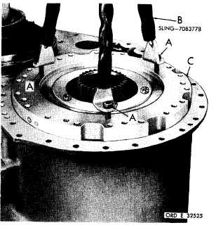
Figure 105 (Step 41)
Remove left-brake anchor assembly (A),
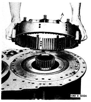
Figure 106 (Step 42)
U s i n g t h r e e 7 / 1 6 - 1 4 - i n c h b o l t s ( A ) , a t t a ch
sling (B) to left-clutch reaction plate assembly
(C). Remove the reaction plate assembly.
|
|