C H A P 5, SEC I I
D I S A S S E M B L Y
76.
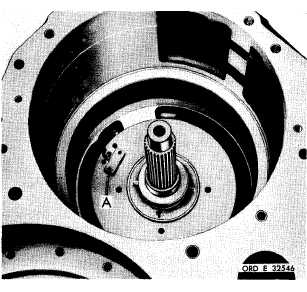
Figure 127 (Step 63)
Remove pitot tube assembly (A).
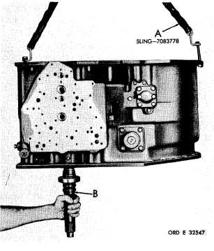
Figure 128 (Step 64)
Using sling (A), lift the transmission housing
and remove converter turbine shaft assembly
(B). Position the transmission housing on its
b o t t o m s i d e.
PAR 7 5 - 7 6
DISASSEMBLY STEPS – LEFT- AND
RIGHT-OUTPUT DRIVE ASSEMBLIES
N o t e. The left- and right-output drive
assemblies are identical with the ex-
ception of the length of two compon-
ents.
The
left-input
shaft
and
left-
saddle assembly are longer than the
corresponding
components
of
the
r i g h t - o u t p u t d r i v e a s s e m b l y . T h e
disassembly procedures are the same
for both assemblies. With the excep-
tion of Step 2, the following illustra-
t i o n s s h o w t h e d i s a s s e m b l y p r o c e-
dures for the right-output drive as-
s e m b l y . S t e p 2 i l l u s t r a t e s t h e l e f t-
output drive assembly, and shows the
difference in size of the input shafts
a n d s a d d l e a s s e m b l i e s o f t h e r i g h t-
and left-output assemblies.
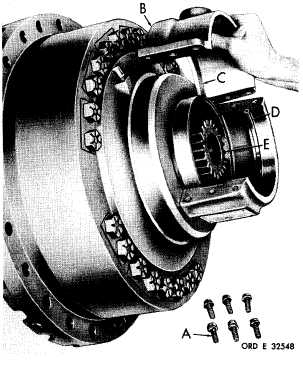
Figure 129 (Step 1)
U s i n g a 9 / 1 6 - i n c h w r e n c h , r e m o v e s i x b o l ts
( A ) a n d l o c k w a s h e r s . R e m o v e o u t p u t d r i ve
c o u p l i n g c a p ( B ) . R e m o v e s e a l ( C ) f r o m c ap
( B ) . R e m o v e a l i n e m e n t r i n g ( D ) a n d i n p ut
shaft (E).
1 0 0
|
|