*C2
CHAP 5, SEC I V .
T O R Q U E C O N V E R T E R R E B U I L D
P A R 8 3
b . T o r q u e C o n v e r t e r P u m p
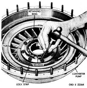
(1) Straighten the tabs of lock strips on
the converter pump hub (fig. 145).
( 2 ) U s i n g a 7 / 1 6 - i n c h w r e n c h , r e m o ve
e i g h t s e l f - l o c k i n g b o l t s a n d f o u r l o c k s t r i ps
retaining the torque converter pump hub in the
converter pump. Remove the hub.
(3) Remove two hook-type seal rings 87
(fig. 373, fold-out 2) from pump nub 88.
(4) Remove retaining ring 92 retaining
bearing 91 in converter pump hub 88. Press
the bearing from the hub.
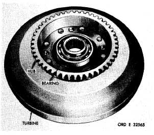
c . T o r q u e C o n v e r t e r T u r b i ne
(1) Do not remove the ball bearing from
t h e t u r b i n e a s s e m b l y , u n l e s s r e p l a c e m e n t is
n e c e s s a r y ( f i g . 1 4 6 ).
Figure 145. Straightening corners of converter pump
hub lock strip
(2) If necessary to remove the bearing,
pry it from the turbine hub.
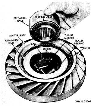
d . T o r q u e C o n v e r t e r S t a t or
(1) Rotating the stator freewheel race
in a clockwise direction, remove it from the
stator assembly (fig. 147).
Figure 146. Torque converter turbine assembly
Figure 147. Removing stator freewheel race and
thrust bearing assembly from stator
1 0 6
|
|