P A R 1 4
6
R I G H T
O U T P U T
R E B U I L D
C H A P 5 , S E C x V I
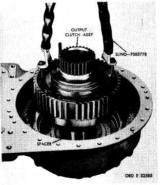
1 . U s i n g s l i n g 7 0 8 3 7 7 8 a n d t w o 5 / 1 6 - 24
b o l t s , i n s t a l l t h e o u t p u t c l u t c h a s s e m b l y ( f i g.
1 6 6 ) . R e m o v e s l i n g a n d l i f t i n g b o l t s a n d i n-
s t a l l t h e t w o r e m a i n i n g 5 / 1 6 - 2 4 x 5 / 8 o u t p u t
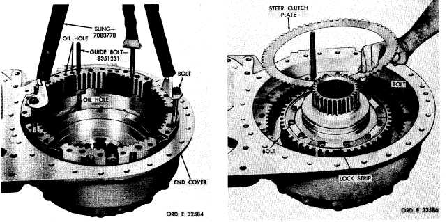
c l u t c h a s s e m b l y b o l t s ( f i g . 1 6 7 ) . T i g h t e n t he
bolts to 14-18 pound-feet torque and bend cor-
n e r s o f t h e l o c k s t r i p s a g a i n s t t h e m .
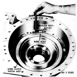
Figure 164. Installing guide bolt used to aline geared
steer clutch and brake components
Figure 165. Installing steer clutch anchor
m . I n s t a l l s i x i n t e r n a l - a n d s e v e n e x -
t e r n a l s p l i n e d s t e e r c l u t c h d i s k s a n d p l a t e s,
beginning with an external-splined clutch plate
( f i g . 1 6 7 ).
Figure 166. Installing output clutch assembly
Figure 167. Installing steer clutch plates
1 2 5
|
|