PAR 1 53
R E A R H O U S I N G R E B U I L D
C H A P 5, SEC X V I I I
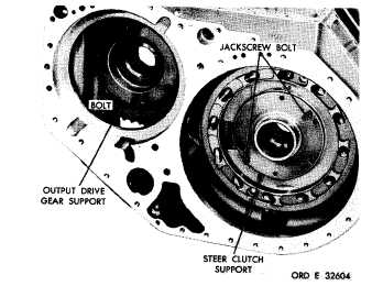
a l . U s i n g a 9 / 1 6 - i n c h w r e n c h , r e m o ve
five self-locking bolts that retain, the output
drive gear bearing support (fig. 185). Use two
of
the
bolts
as
jackscrews
to
loosen
the
sup-
p o r t . R e m o v e t h e s u p p o r t.
am. Position the transmission rear hous-
ing on its left side (fig. 186).
Figure 185. Transmission rear housing — left-side view
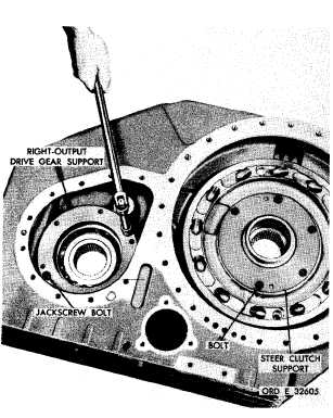
a n . U s i n g a 9 / 1 6 - i n c h w r e n c h , r e m o v e
f i v e s e l f - l o c k i n g b o l t s r e t a i n i n g t h e o u t p ut
d r i v e g e a r b e a r i n g s u p p o r t . U s e t w o o f t h e
bolts as jackscrews to loosen the support (fig.
1 8 6 ) . R e m o v e t h e s u p p o r t.
a o . U s i n g a 9 / 1 6 - i n c h w r e n c h , r e m o v e
f i v e s e l f - l o c k i n g b o l t s t h a t r e t a i n t h e r i g ht
steer clutch support (fig. 186). Use two of the
bolts as jackscrews to loosen the support. Re-
m o v e t h e s u p p o r t.
a p . If bearings 25 and 27 (fig. 377, fold-
out 6) or bearing assembly 35 (fig. 378, fold-
out 7) or bearing assembly 1 (fig. 380, fold-
o u t 9 ) n e e d t o b e r e p l a c e d , r e m o v e b e a r i ng
races from supports 24 and 28 (fig. 377, fold-
out 6) and supports 34 (fig. 378, fold-out 7)
and 2 (fig. 380, fold-out 9).
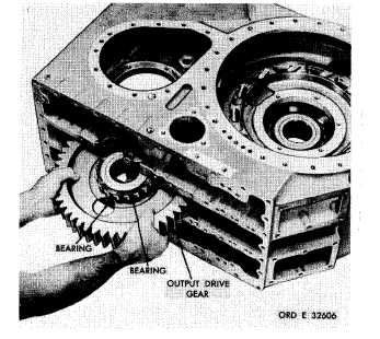
a q . R e m o v e t h e o u t p u t d r i v e g e a r w i th
i n n e r - b e a r i n g a s s e m b l i e s ( f i g . 1 8 7 ) . D o n ot
remove the inner bearing assemblies from the
g e a r u n l e s s r e p l a c e m e n t i s n e c e s s a r y .
a r . Remove the output driven gear with
i n n e r b e a r i n g a s s e m b l i e s ( f i g . 1 8 8 ) . D o n ot
remove the inner bearing assemblies from the
g e a r , u n l e s s r e p l a c e m e n t i s n e c e s s a r y .
a s . U s i n g a 9 / 1 6 - i n c h w r e n c h , r e m o v e
four self-locking bolts and flat washers that
Figure 186. Removing output drive gear support
Figure 187. Removing (or installing) output drive gear
1
3
3
|
|