PAR 1 5 6
R E A R H O U S I N G R E B U I LD
C H A P 5, SEC X V I II
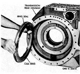
Figure 190.
Removing (or installing) left-brake apply
cam stationary ring
h.
I n s t a l l t h e o u t p u t d r i v e n g e a r w i t h
bearing inner race assemblies into tine rear
housing (fig. 188).
i . I f b e a r i n g s w e r e r e m o v e d f r o m t h e
o u t p u t d r i v e g e a r , i n s t a l l a n i n n e r - b e a r i ng
race assembly on each side of the gear (fig.
1 8 7 ) . P r e s s b e a r i n g s u n t i l t h e y a r e f i r m ly
seated on the gear.
j.
Install the output drive gear with the
b e a r i n g i n n e r - r a c e a s s e m b l i e s i n t o t h e r e ar
housing (fig. 187).
k . I f b e a r i n g o u t e r r a c e s w e r e r e m o v e d
from supports 24 and 28 (fig. 377, fold-out 6)
and 34 and 2 (figs, 378 and 380, fold-outs 7
and 9), install outer bearing races in the sup-
p o r t s.
l . I n s t a l l t h e r i g h t - s t e e r c l u t c h s u p p o rt
and secure with five 3/8-16 self-locking bolts
( f i g . 1 8 6 ) . T o r q u e t h e b o l t s t o 3 6 - 4 3 p o u n d -
feet.
m . I n s t a l l t h e r i g h t - o u t p u t d r i v e g e ar
support and secure with five 3/8-16 self-lock-
ing bolts (fig. 186). Torque the bolts to 36-43
p o u n d - f e e t .
n . Install the left-output drive gear sup-
port and secure with five 3/8-16 self-locking
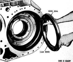
Figure 191. Removing (or installing) right-brake apply
cam stationary ring
b o l t s ( f i g . 1 8 5 ) . T o r q u e t h e b o l t s t o 3 6 - 43
p o u n d - f e e t.
o.
I n s t a l l t h e l e f t - s t e e r c l u t c h s u p p o rt
and secure with five 3/8-16 self-locking bolts
(fig, 185). Torque bolts to 36-43 pound-feet.
p . If bearings 78 and 80 (fig. 379, fold-
out 8) were removed from spindle 79, install
the bearings, pressing against the numbered
side of the bearing cage. Press each bearing,
0.120 inch below the end of the spindle.
q . I n s t a l l t h e l e f t - b r a k e c a m a s s e m b l y,
spring and spindle assembly in rear housing.
Install the spring on the brake cam and posi-
tion these parts in the housing, then install the
spindle assembly as shown (fig. 184).
r . I n s t a l l t h e r e t a i n i n g r i n g a n d s p a c er
on left-brake apply shaft (fig. 183).
s . I f b e a r i n g o r o i l s e a l w a s r e m o v e d,
i n s t a l l i n r i g h t - b r a k e a p p l y s h a f t ( f i g . 1 8 3 ).
Install bearing, pressing against the numbered
side of the cage, 0.960 inch below the end of
the shaft. Install the new replacement oil seal,
l i p s i d e o f s e a l t o w a r d t h e i n s i d e , i n t o t h e
shaft end until it is firmly seated against its
shoulder in the shaft.
t . Install the washer and retaining ring
on the right-brake apply shaft (fig. 183).
1 3 5
|
|