C H A P 5, S E C X I X
L E F T , R I G H T S T E E R P L A N E T A R I E S R E B U I L D
PAR 1 5 8 - 1 60
Figure 203. Removing (or installing) steer planetary
carrier ring gear assembly
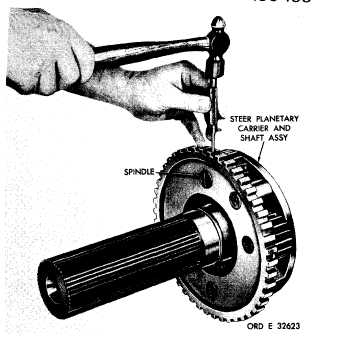
g . U s i n g a h a m m e r a n d p u n c h , r e m o ve
four steer planetary carrier spindle lock pins
(fig. 204).
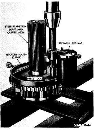
h . U s i n g r e p l a c e r p l a t e 8 3 5 1 4 9 2 , r e-
placer 8351266 and a suitable press tool, press
four spindles from the planetary shaft and car-
r i e r a s s e m b l y ( f i g . 2 0 5 ).
i . R e m o v e t h e s t e e r p l a n e t a r y c a r r i e r
pinions (6, fig. 378, fold-out 7), roller bear-
ings 7, spacers 5 and 8, and thrust washers
4 and 9 from carrier 3.
1 5 9 . C L E A N I NG
Refer to par. 71 for cleaning recommen-
d a t i o n s .
1 6 0 . I N S P E C T I O N A N D R E P A IR
R e f e r t o p a r . 7 2 f o r g e n e r a l i n s p e c t i o n
and repair recommendations. Repair and re-
b u i l d p o i n t s o f m e a s u r e m e n t f o r f i t s , c l e a r-
ances and wear limits are indicated by small,
lower case letters in figs. 378 and 380, fold-
outs 7 and 9. Refer to pars. 241 and 243 for
wear limits information.
1 4 0
Figure 204. Removing (or installing) spindle lock pin
Figure 205. Removing steer planetary carrier and shaft
assembly spindle
|
|