*C2
*C2
PAR 1 61
L E F T , R I G H T S T E E R P L A N E T A R I E S R E B U I LD
CHAP 5, SEC X I X
161. ASSEMBLY (figs. 378 and 380,
fold-outs 7 and 9)
N o t e . C h i l l s t e e r p l a n e t a r y c a r r i er
spindles 11 (fig. 378, fold-out 7) in
dry ice for approximately one hour,
prior to installation.
a . P l a c e s t e e r p l a n e t a r y s h a f t a n d c a r-
rier, shaft end up, in a press.
b . G r e a s e t h e i n s i d e d i a m e t e r o f t he
planetary carrier pinion 6.
c .
I n s e r t 2 5 s p i n d l e b e a r i n g r o l l e r s 7
into the pinion bore. Refer to fig. 215.
d . Place a thrust washer 4 and a spacer
5 on alining tool 8351214. Refer to fig. 215.
e . Insert alining tool 8351214 with washer
and spacer into the pinion. Refer to fig. 215.
f . I n s t a l l s p a c e r 8 a n d t h r u s t w a s h e r 9
( f i g . 3 7 8 , f o l d - o u t 7 ) o v e r t h e a l i n i n g t o o l.
Remove the alining tool.
Figure 206. Installing steer planetary carrier and
shaft spindle
g . Slide the pinion and its related parts
into its location in the planetary carrier as-
s e m b l y 3 f r o m w h i c h i t w a s r e m o v e d . U s i ng
alining tool 8351214, aline the pinion and re-
lated parts in the carrier. Refer to fig. 221.
Remove the alining tool.
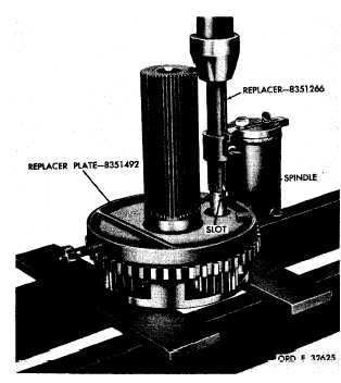
h . Install the replacer plate 8351492 and
spindle replacer 8351266 on the carrier and
position the planetary carrier spindle for in-
stallation (fig. 206).
N o t e . Be sure that the slot on the
spindle is indexed properly with its
lock pin bore in the carrier (fig. 206).
i . U s i n g a p r e s s , i n s t a l l t h e p l a n e t a ry
c a r r i e r s p i n d l e i n t h e c a r r i e r ( f i g . 2 0 6 ).
Spindle replacer 8351266 will bottom against
the carrier when the spindle is properly po-
sitioned in the carrier.
j . I n s t a l l l o c k p i n 1 0 ( f i g . 3 7 8 , f o l d - o ut
7) using a hammer and punch. Drive lock pin
in 0.030 to 0.060 inch below the carrier sur-
face (fig. 204). Stake metal over the pin.
m . Install the thrust washer in the ring
gear (fig. 203).
n . I n s t a l l t h e i n t e r n a l - s n a p r i n g i n t he
ring gear (fig. 203).
o . I n s t a l l t h e s t e e r p l a n e t a r y c a r r i er
ring gear in the brake hub (fig. 203).
p . Install the steer planetary shaft and
c a r r i e r a s s e m b l y ( f i g . 2 0 2 ).
q . Install the retaining ring that retains
the steer planetary shaft and carrier assembly
(fig. 202).
1 4 1
|
|