*C2
*C2
*C2
C H A P 5, SEC X X I
L E F T , R I G H T O U T P U T C L U T C H E S R E B U I LD
PAR 1 6 8 - 1 69
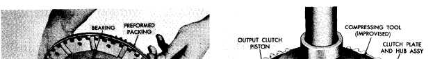
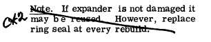
Figure 209. Removing (or installing) geared steer sun
gear assembly
c . U s i n g a l / 2 - i n c h w r e n c h , r e m o v e 12
bolts, six lock plates and three retainers from
the clutch assembly (fig. 208).
d . U s i n g t w o 5 / 1 6 - 2 4 b o l t s , r e m o v e t he
g e a r e d s t e e r s u n g e a r a s s e m b l y f r o m t he
clutch plate and hub assembly (fig. 209).
N o t e . T h e s u n g e a r a s s e m b l y m ay
bind in the hub, due to the preformed
packing. If so, pry it loose.
e . R e m o v e t h e p r e f o r m e d p a c k i n g f r om
geared steer sun gear assembly (fig. 209).
f. Do not remove the bearing and retain-
ing ring from the sun gear assembly unless
replacement of the bearing is necessary (fig.
209). If necessary, remove the retaining ring
and press out the bearing.
g.
Remove
the
output
clutch
hub
and
clutch plates from the clutch plate hub assem-
bly (fig. 209).
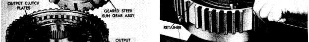
h.
Using
a
hydraulic
press
and
com-
pressing tool (fig. 38) against the piston return
1 4 4
Figure 210. Removing (or installing) retaining ring for
piston return spring retainer
spring retainer, compress the springs and re-
move the retaining ring (fig. 210).
i. Remove retainer 43 (fig. 377, fold-out
6) and eighteen piston return springs 44.
j. Turn the clutch plate and hub assembly
over, and bump the clutch piston from the hub
(fig. 210).
k . Remove ring seal 38 and expander 39
(fig. 377, fold-out 6) from clutch piston 41.
l. Remove ring seal 37 and expander 36
from clutch plate and hub assembly 35.
1 6 9 . C L E A N I NG
Refer to par. 71 for cleaning recommen-
d a t i o n s.
|
|