*C2
*C2
*C2
*C2
C H A P 5, SEC X X V II
H I G H C L U T C H R E B U I L D
PAR 1 9 6 - 1 98
f . P l a c e a s p a c e r 2 1 o r 2 4 a n d t h r u st
washer 20 or 25 over the other end of alining
t o o l . R e m o v e a l i n i n g t o o l.
g . Slide the pinion, with its related parts
into the location in the carrier 18 from which
it was removed. Using alining tool 8351208,
aline the pinion, rollers, spacers and washers.
Refer to fig. 221.
Remove the alining tool.
the
f o r
h . I n s t a l l s p i n d l e r e p l a c e r 8 3 5 1 2 6 6 on
planetary carrier and position the spindle
installation (fig. 226).
N o t e . B e s u r e t h a t t h e s l o t o n t he
spindle is indexed properly with its
lock pin bore in the carrier (fig. 226).
i.
With
a
press
and
spindle
replacer
8351266, install the planetary carrier spindle
(fig. 226). Press in the spindle to within 0.010
inch of the carrier surface.
j. Install a lock pin, using a hammer and
punch (fig. 224). Drive the pin 0.030 to 0.060
b e l o w t h e a d j a c e n t c a r r i e r s u r f a c e . S t a ke
metal over the pin.
k . I n s t a l l t h e r e m a i n i n g t h r e e s p i n d l es
19 (fig. 376, fold-out 5) and pinions 22, with
rollers 23, spacers 21 and 24, thrust washers
20 and 25 and lock pins 17 in the same manner
as described in b through j , a b o v e.
l. I n s t a l l t h e i n t e r m e d i a t e - r a n g e p l a n e -
tary carrier assembly onto the low-range ring
gear. Install the retaining ring (fig. 223).
Section XXVII. HIGH-RANGE CLUTCH — REBUILD
1 9 7 . D E S C R I P T I O N
Refer to par. 11 for the description of the
high-range clutch.
1 9 8 . D I S A S S E M B L Y ( f i g . 3 7 5 , f o l d - o u t 4)
N o t e . All related items not covered
in a through i, below, were removed
from the transmission as outlined in
par. 75, steps 126 and 127. No fur-
t h e r d i s a s s e m b l y o f t h e s e p a r t s is
r e q u i r e d.
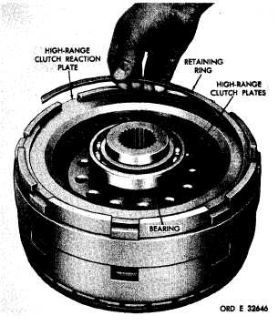
a . Remove the retaining ring that retains
the high-range clutch reaction plate (fig. 227).
Remove the reaction plate.
b . R e m o v e t h e h i g h - r a n g e c l u t c h p l a t es
(fig. 227).
c . Using bearing puller, remove the bear-
ing from the hub of the high-range clutch hous-
ing (fig. 228).
1
5
4
Figure 227. Removing (or installing) retaining ring that
retains high-range clutch reaction plate
|
|