*C2
C H A P 5, SEC X X V I I I
T R A N S M I S S I O N H O U S I N G R E B U I LD
P A R 2 0 3 - 2 0 6
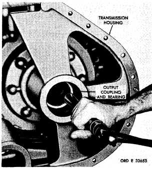
Figure 234. Removing transmission output coupling
and bearing
j . P o s i t i o n t h e t r a n s m i s s i o n h o u s i n g to
rest on its bottom. Using a hammer and soft
drift, drive out the output coupling and ball
bearing (fig. 234).
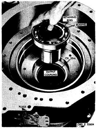
Figure 235. Transmission output coupling and bearing
r e m o v ed
k . R e m o v e t h e b e a r i n g f r o m t h e o u t p ut
coupling (fig. 235).
2 0 5 . I N S P E C T I O N A N D R E P A IR
l . D o n o t r e m o v e t h e i n t e r n a l - r e t a i n i ng
R e f e r t o p a r . 7 2 f o r g e n e r a l i n s p e c t i on
ring from the output coupling unless replace-
and repair recommendations. Repair and re-
m e n t i s n e c e s s a r y ( f i g . 2 3 5 ) . I f n e c e s s a r y,
b u i l d p o i n t s o f m e a s u r e m e n t f o r f i t s , c l e a r-
remove the retaining ring.
ances and wear limits are indicated by small,
lower case letters in fig. 375. fold-out 4. Re-
m . Do not remove the oil seal from the
fer to par. 238 for wear limits information.
t r a n s m i s s i o n h o u s i n g u n l e s s r e p l a c e m e n t is
n e c e s s a r y ( f i g . 2 3 5 ) . I f n e c e s s a r y , d r i v e t he
2 0 6 . A S S E M B L Y ( f i g . 3 7 5 , f o l d - o u t 4)
oil seal out of the housing.
a . Install any plugs removed from the
n . I f n e c e s s a r y , t h e v a r i o u s p l u g s m ay
transmission main housing (figs. 233 and 235).
b e r e m o v e d f r o m t h e h o u s i n g t o a i d i n t he
c l e a n i n g o f t h e o i l p a s s a g e s i n t h e h o u s i ng
b . P o s i t i o n t h e t r a n s m i s s i o n h o u s i n g on
(figs. 233 and 235).
its side. Using replacer 8351210, install the
oil seal, lip side up, in its transmission hous-
ing bore (fig. 235). Be sure the seal is firmly
2 0 4 . C L E A N I NG
seated against its shoulder in the housing.
Refer to par. 71 for cleaning recommen-
c . I n s t a l l t h e b e a r i n g o n t o t h e o u t p u t
d a t i o n s.
coupling (fig. 235).
1 5 8
|
|