CHAP 5, SEC XX XII
L E F T , R I G H T O U T P U T S H A F T R E B U I L D
P A R 222-2:!5
Section XXXII.
LEFT- AND RIGHT-OUTPUT SHAFT ASSEMBLY -- REBUILD
222. DESCRIPTION
Refer to pars. 26 and 27 for description
of the left- and right-output shaft assemblies.
223. DISASSEMBLY
a.
Left - output Shaft Assembly
—
Ifig. 385, fold-out 14)
(1) Using a 3/16-inch hexagon wrench,
remove three pipe plugs from output shaft as-
sembly (fig. 237).
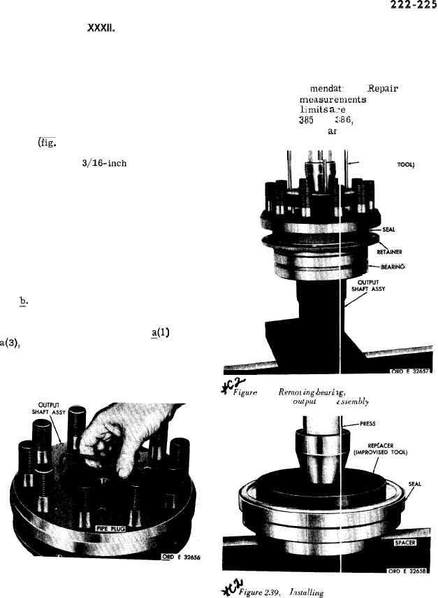
(2) Using a bearing remover, remove
the output shaft bearing and related parts (fig.
238). Use the short-pin side of the special
tool first, then the long-pin side, to complete
the removal of the bearing.
(3) Remove seal 46 (fig. 385, fold-out
14) and preformed packing 45 from spacer 44.
Q. Right-output Shaft Assembly. The
left - and r i g h t- output shaft assemblies are
identical, therefore the disassembly proce-
dure is the same as described in ~(l) through
a(3), above.
—
224. CLEANING
Refer to par, 71 for cleaning recommen-
dations.
Figure 237. Removing pipe plugs from output shaft
assembly
162
225. INSPECTION AND REPAIR
Refer to par. 72 for general inspection
and repair recoin mendat. ens. .Repair and re-
build points of measuren]ents for fits, clear-
ances and wear lilmits a::e indicated by small
letters in figs. 385 and :~86, fold-outs 14 and
15. Refer to pars, 248 ar d 249 for wear limits
information.
II
J Ill I
l--
BEARING REMOVER
(IMPROVISED TOOL)
l--WRING
+-Figure .238. Remoz ing beari ag, retainer and seal from
otiput shaft c ssembly
*~iwre2.W.
l~stalling seal onto output shaft spacer
|
|